Motor drive apparatus equipped with discharge circuit of capacitor of DC link
a technology of dc link and discharge circuit, which is applied in the direction of dc-ac conversion without reversal, process and machine control, instruments, etc., can solve the problems of poor work efficiency, maintenance and replacement work or recovery work may not be performed, and electric shock, so as to achieve the effect of reducing work efficiency, reducing work intensity and increasing capacity
- Summary
- Abstract
- Description
- Claims
- Application Information
AI Technical Summary
Benefits of technology
Problems solved by technology
Method used
Image

Examples
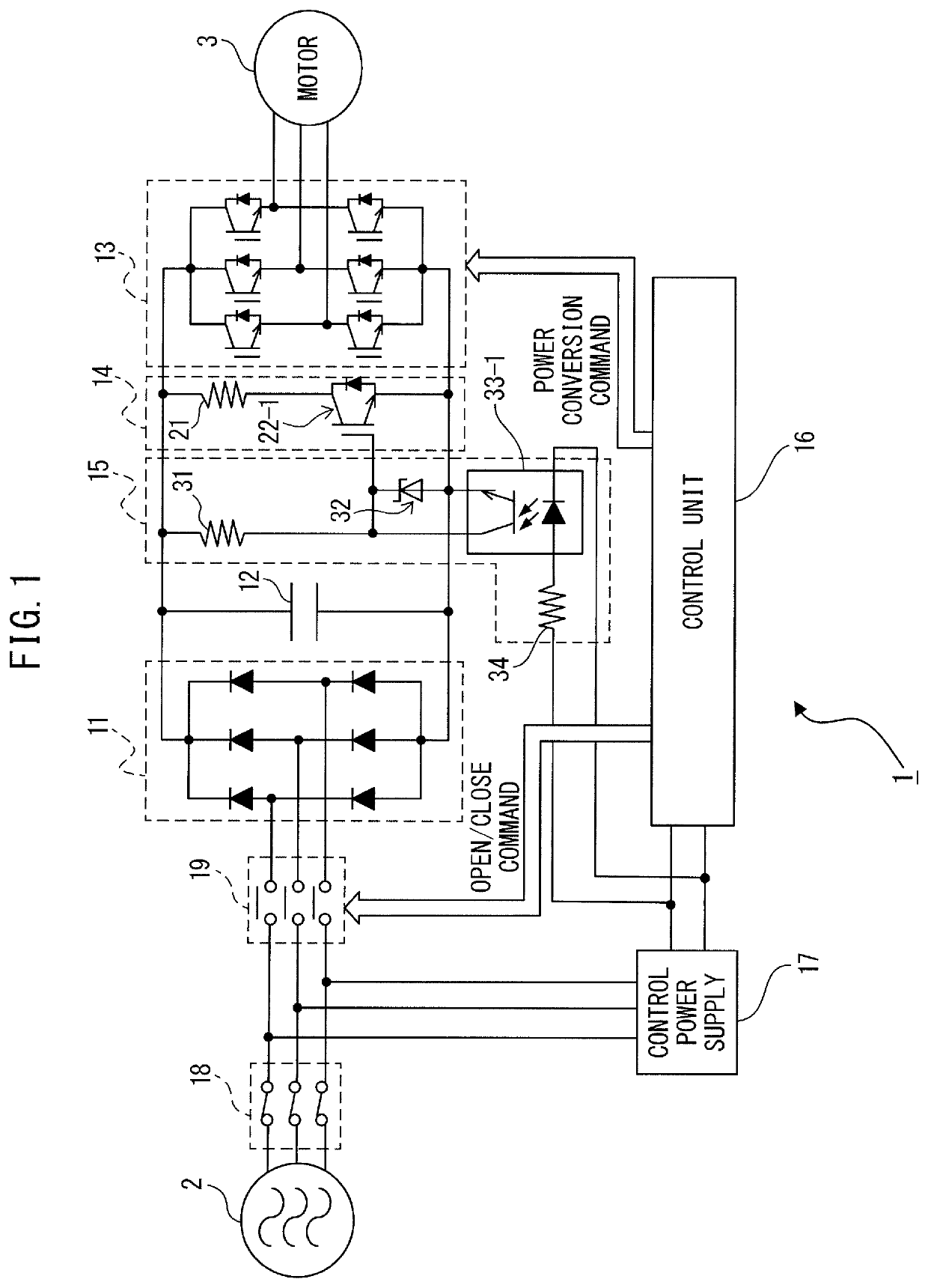
first embodiment
[0042]Furthermore, an operation of the motor drive apparatus 1 according to the present disclosure is described.
[0043]In a condition in which the motor drive apparatus 1 is driving the motor 3, both the breaker 18 and the electromagnetic contactor 19 are in a closed circuit state, the AC power supply 2 and the converter 11 are electrically connected to each other, and the converter 11 converts AC power supplied from the AC power supply 2 into DC power and then outputs the DC power to the DC link. When receiving a power conversion command from the control unit 16, the inverter 13 performs a power conversion operation (powering operation) of converting DC power in the DC link into AC power for motor drive and then outputting the AC power to the motor 3, or a power conversion operation (regenerating operation) of converting AC power generated in the motor 3 into DC power and then returning the DC power to the DC link side. The control unit 16 is operating by power supplied from the con...
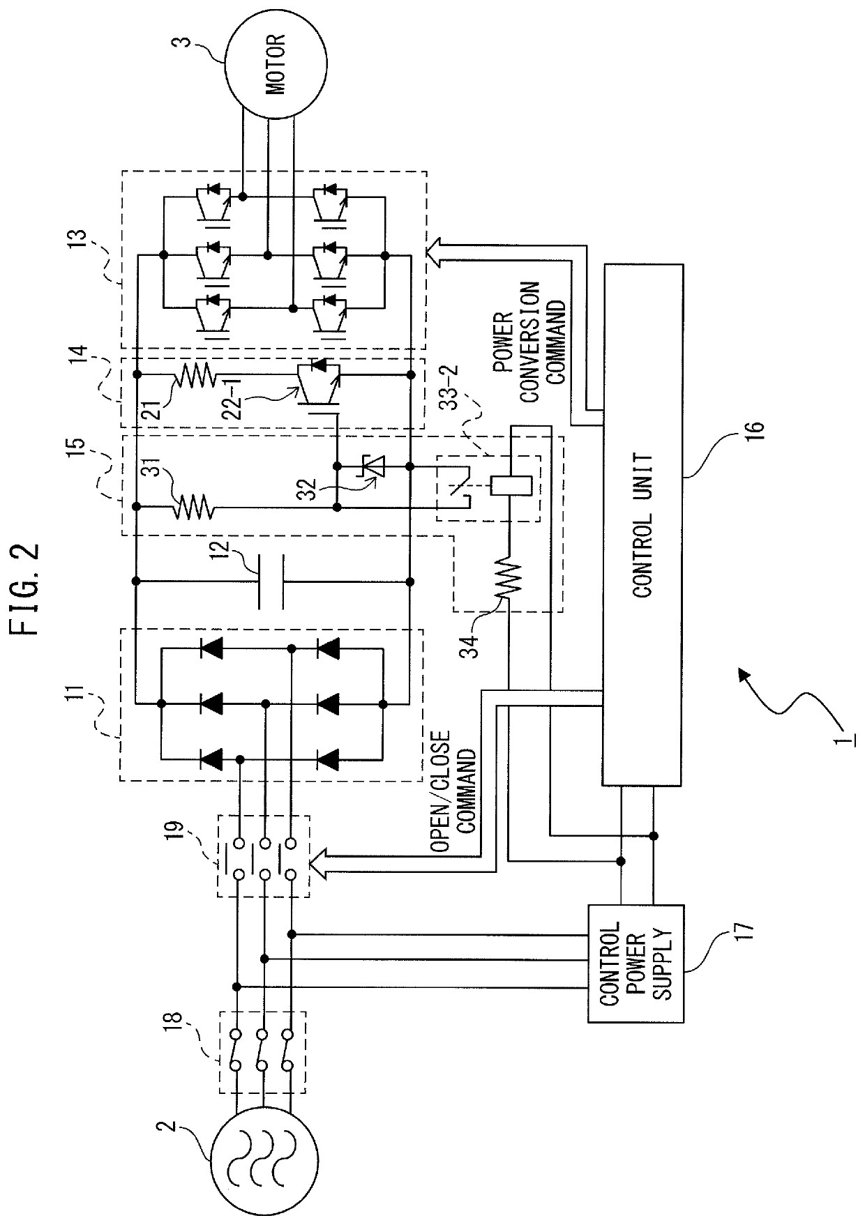
second embodiment
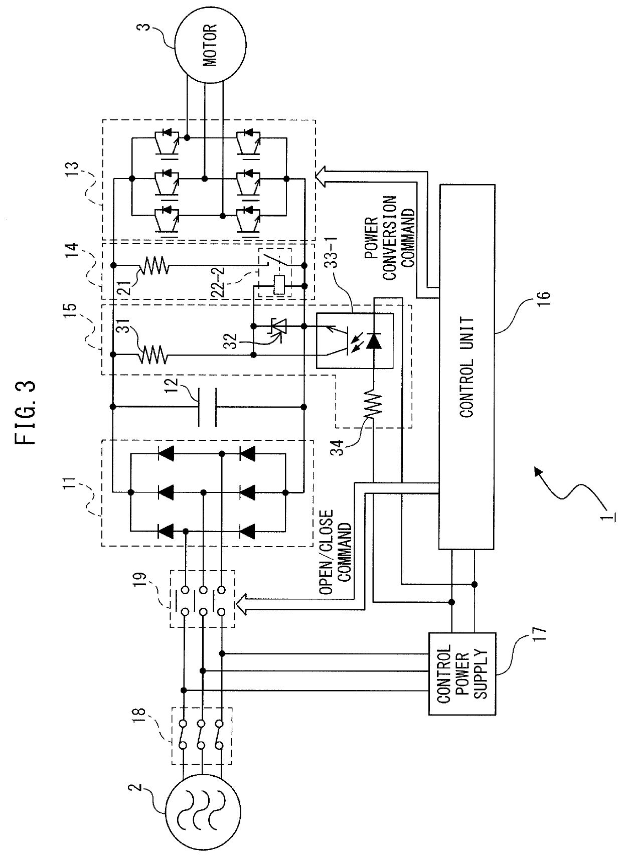
[0051]FIG. 5 is a diagram illustrating a motor drive apparatus according to the present disclosure.
[0052]In FIG. 5, a switch for power supply disappearance detection is configured by a B contact relay 33-3 instead of the photo coupler 33-1 described with reference to FIGS. 1 and 3. As illustrated in FIG. 5, the discharge circuit drive unit 15 includes a current limiting resistor 31, a constant voltage output unit 32, and the B contact relay 33-3 as a switch for power supply disappearance detection.
[0053]The current limiting resistor 31 includes a first terminal connected to a positive side terminal of a capacitor 12, and a second terminal to which current input from the first terminal is output.
[0054]The B contact relay 33-3 as the switch for power supply disappearance detection is a “normally-on” type relay in which a contact is turned off when current is flowing therein, and the contact is turned on when current is not flowing therein. The B contact relay 33-3 includes an input te...
PUM
 Abstract
Description
Claims
Application Information
 - R&D
- Intellectual Property
- Life Sciences
- Materials
- Tech Scout
- Unparalleled Data Quality
- Higher Quality Content
- 60% Fewer Hallucinations
Browse by: Latest US Patents, China's latest patents, Technical Efficacy Thesaurus, Application Domain, Technology Topic, Popular Technical Reports.
© 2025 PatSnap. All rights reserved.Legal|Privacy policy|Modern Slavery Act Transparency Statement|Sitemap|About US| Contact US: help@patsnap.com