System for effecting and controlling oscillatory pressure within balloon catheters for fatigue fracture of calculi

a technology of calculus and oscillatory pressure, which is applied in the field of system for controlling oscillatory pressure within balloon catheters for calculi fatigue fracture, can solve the problems of balloons not being able to adequately expand and prepare the lesion, calcified structures or calcified lesions are particularly difficult to treat, and apply large stress to the patient's blood vessels, so as to reduce the overall volume, reduce the overall system pressure, and improve the sensitivity of back-sensing

Active Publication Date: 2020-02-13
RGT UNIV OF MICHIGAN
View PDF0 Cites 11 Cited by
  • Summary
  • Abstract
  • Description
  • Claims
  • Application Information

AI Technical Summary

Benefits of technology

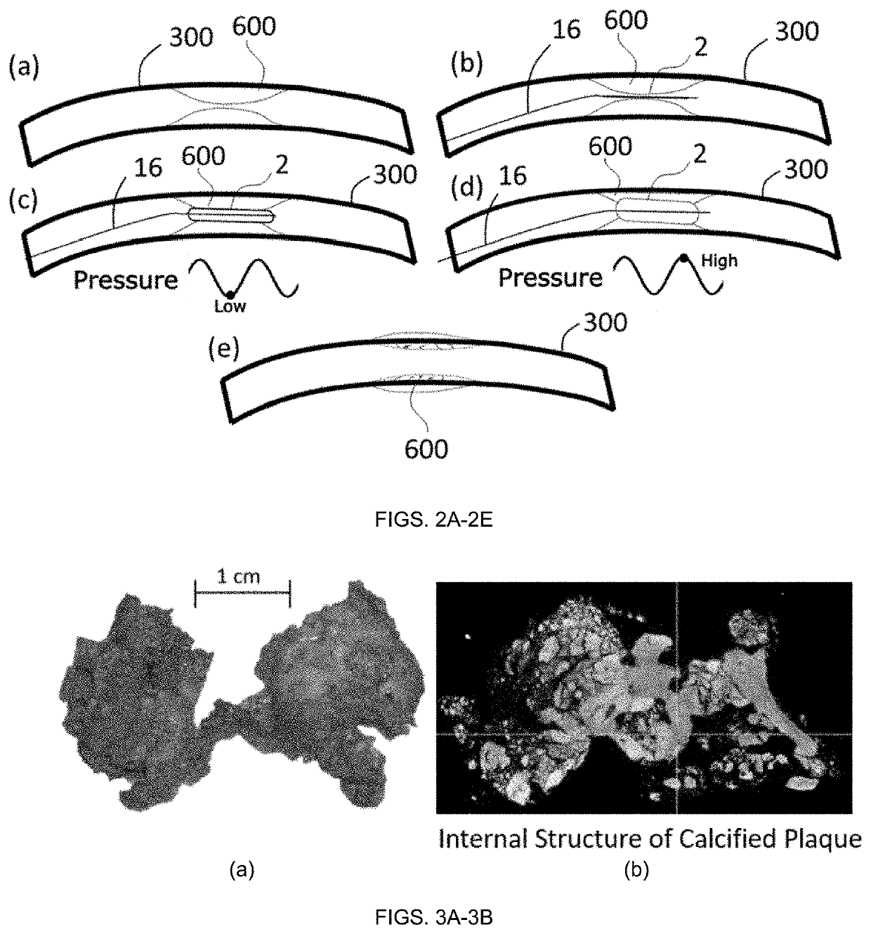
[0010]Generally, the various embodiments described herein enable dynamic balloon angioplasty (DBA), a technique that uses pressure oscillations with a generalized waveform (in some embodiments, harmonic, or frequency-specific, pressure waveform oscillations) to effectively and safely fracture calcified lesions during angioplasty. The concept of DBA for treating arterial calcified plaque is illustrated in FIGS. 2A-2E. In DBA, a catheter 16 with balloon 2 is deployed to the vessel 300 with calcification 600 (FIG. 2B). Through the angioplasty balloon, the plaque is subjected to high-frequency pressure oscillations (FIGS. 2C-2D). In the low-pressure phase of the oscillations (FIG. 2C), the balloon pressure is reduced to near the minimum pressure needed to achieve balloon inflation, typically 1-2 atm. In the high-pressure phase of the oscillations (FIG. 2D), the balloon is inflated to a peak pressure, set by the physician. Typical peak inflation pressures may be from above the low-pressure range to the balloons' max rated pressure, which could be 25 atm or more. Pressure cycling of the balloon in this manner induces cyclic loading of the calcified plaque 600 below the calcified plaque's rupture stress yet in the plastic deformation zone. Calcified plaque 600 from a human femoral artery is shown in FIG. 3A. A high-resolution computed tomography scan of the calcified plaque of FIG. 3A, shown in FIG. 3B, demonstrates a highly irregular interior and surface. The heterogeneity of the calcified plaque interior is composed of many microfractures with sharp corners. Through the fracture mechanisms described herein, the cyclic loading described in FIG. 2 causes cyclic stresses at these sharp corners near plaque microfractures and irregular surfaces. The cyclic stress initiates and grows these sharp corners, which expand the microfractures into larger macroscopic fractures. The growth of these microfractures leads to the more complete fracture of plaque at lower inflation pressures compared to static pressure. Higher frequency pressure cycles and higher-pressure differences between the cycles is expected to increase the effectiveness of this crack growth mechanism. By generating controlled high-frequency pressures cycles in an angioplasty balloon, DBA is expected to lower the required balloon pressure for fracturing calcified plaque, improve stent deployment, improve and control drug delivery for drug-coated balloons, stress-soften soft, lipid-core atheromatous plaques, expand calcified in-stent restenoses, and fracture calcifications on diseased cardiac valves leaflets and improve balloon-based expansion and deployment of prosthesis and devices.
[0091]To improve the sensitivity of back-sensing of calcified plaque fracture, the exemplary angioplasty catheter described herein can be used. To demonstrate the effect of this catheter, a simulation of the improved back-sensing due to the increased flow channel lumen is shown in FIGS. 23A and 23B. A conventional angioplasty balloon and a balloon with an exemplary angioplasty catheter are pressurized to the same pressure and fracture (rapid balloon expansion) is simulated. Under similar conditions, there is an increased sensation from the pressure transducer of the pressure drop from the balloon with an exemplary angioplasty catheter (FIG. 23A). The corresponding Gaussian Derivative indicates a sharper and higher magnitude in the exemplary angioplasty balloon and catheter (FIG. 23B). Therefore, to improve back-sensing capabilities for sensing calcified plaque fracture, the exemplary angioplasty catheter can be used.

Problems solved by technology

The calcified structures or calcified lesions have proven to be particularly challenging to treat.
These high pressures apply large stresses to the patient's blood vessels.
Physicians often must weigh the risk of increasing balloon pressure, which may cause vessel dissection, a significant adverse event, with leaving the plaque untreated.
Even with high pressures in conventional balloon angioplasty, the balloon may fail to sufficiently expand and prepare the lesion for stent placement.
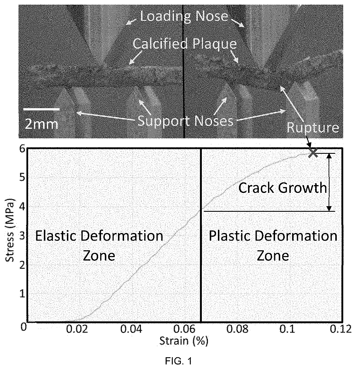
When the calcified plaque is loaded to any stress in the plastic deformation zone, permanent deformation of the structure through crack growth occurs.
However, to achieve rupture, high stresses in the calcified plaque are required, which leads to surrounding vessel injury.
This injury occurs frequently during the conventional static balloon angioplasty process because balloon pressures must induce stresses large enough in the calcified plaque to achieve rupture.
Therefore, there exists a need for a change in practice from conventional, static balloon angioplasty in which the plaque is held solely in tension (and results in vessel injury due to the high pressures required to generate rupture) to dynamic balloon angioplasty in which the plaque is repeatedly loaded using an oscillating balloon to promote microcrack propagation and induce plaque fracture at a stress significantly lower than the initial plaque structural strength.

Method used


Image

  • System for effecting and controlling oscillatory pressure within balloon catheters for fatigue fracture of calculi
  • System for effecting and controlling oscillatory pressure within balloon catheters for fatigue fracture of calculi
  • System for effecting and controlling oscillatory pressure within balloon catheters for fatigue fracture of calculi

Examples


Embodiment Construction

[0049]Example embodiments will now be described more fully with reference to the accompanying drawings.

[0050]Example embodiments are provided so that this disclosure will be thorough, and will fully convey the scope to those who are skilled in the art. Numerous specific details are set forth such as examples of specific components, devices, and methods, to provide a thorough understanding of embodiments of the present disclosure. It will be apparent to those skilled in the art that specific details need not be employed, that example embodiments may be embodied in many different forms and that neither should be construed to limit the scope of the disclosure. In some example embodiments, well-known processes, well-known device structures, and well-known technologies are not described in detail.

[0051]The terminology used herein is for the purpose of describing particular example embodiments only and is not intended to be limiting. As used herein, the singular forms “a,”“an,” and “the” ...


PUM


Abstract

A dynamic balloon angioplasty system for applying a dynamic pressure to fracture hardened materials embedded within an elastic conduit. The system having a pressure source system outputting at least a first predetermined pressure from a pressure source outlet, and an angioplasty unit fluidly coupled to the pressure source outlet receiving at least the first predetermined pressure. The angioplasty unit having an angioplasty inflation device, an angioplasty balloon connector, and an oscillating mechanism selectively actuated to output a plurality of pressure pulses to the angioplasty balloon via a fluid communication path. A control system is configured to determine an optimal hydraulic pressure oscillation frequency and amplitude for a given procedure and output a control signal to the oscillating mechanism, and monitor a pressure signal to detect fracture of the hardened material within the elastic conduit or system failure or leakage.

Description

CROSS-REFERENCE TO RELATED APPLICATIONS[0001]This application is a continuation-in-part of International Application No. PCT / US2019 / 027139, filed on Apr. 12, 2019, which claims the benefit of U.S. Provisional Application No. 62 / 656,699, filed on Apr. 12, 2018. The entire disclosures of the above applications are incorporated herein by reference.FIELD[0002]The present disclosure relates to a method, apparatus, and control mechanism for creating pressure oscillations with large, controllable amplitudes and high frequencies in a balloon-based medical device. Embodiments of this apparatus relate to automated and controlled methods of creating hydraulic-pressure oscillations to perform tasks such as, for example, fracturing hardened materials embedded within elastic conduits. The overall system may be used, for example, for multiple medical applications including, but not limited to, treatment of cardiovascular atherosclerosis, treatment of calcified valves, or a genitourinary device for...

Claims


Application Information

Patent Timeline
Patent Type & Authority Applications(United States)
IPC IPC(8): A61M25/10A61B17/22
CPCA61B17/22012A61M25/104A61B2017/22001A61M2205/0216A61B2017/22038A61B2017/22062A61M25/10185A61M2205/3344A61M25/10182A61B2017/22081A61B2017/22014A61B2017/22051A61B2017/00017A61B2017/00548A61B2017/00132A61B2017/00185A61B2017/00194A61M25/10184A61M25/10187A61B2017/00154A61B2017/00539A61B2017/00181
Inventor CHISENA, ROBERTGURM, HITINDER S.HILDNER, MATTHEWZHENG, YIHAOSHIH, ALBERT
Owner RGT UNIV OF MICHIGAN
Why Eureka
Try Eureka