Microfluidic system for digital polymerase chain reaction of a biological sample, and respective method

a microfluidic system and polymerase chain reaction technology, applied in fluid controllers, laboratory glassware, chemistry apparatus and processes, etc., can solve the problems of increased surface-to-volume ratio, undesired sample liquid vaporization, and gas bubble generation

Pending Publication Date: 2020-02-20
ROCHE MOLECULAR SYST INC
View PDF2 Cites 1 Cited by
  • Summary
  • Abstract
  • Description
  • Claims
  • Application Information

AI Technical Summary

Benefits of technology

[0027]flowing an initial sealing liquid through the flow channel of the microfluidic device for sealing each reaction area of the array of reaction areas after the microfluidic device has been filled with the sample liquid, thereby pushing remaining sample liquid out of the microfluidic device,

Problems solved by technology

However, when actually miniaturizing the reaction chamber volumes to become microfluidic structures of a microfluidic device in order to generate the desired small dimensions, several already known problems increase, such as problems related to the increased surface-to-volume ratio, or undesired sample liquid vaporization, and in particular the undesired generation of gas bubbles within the liquid provided in or streamed through the microfluidic device.
Lying in the focus of the present disclosure, gas bubbles existent in a liquid within a microfluidic structure can constitute a severe problem since gas bubbles circulating through a microfluidic system can—as a side aspect-not only damage the microfluidic structure of any kind of sensor used therein, but mainly can also damage the biological sample of interest due to causing undesired mixing of samples in neighboring microwells, resulting in cross-contamination and, thus, substantial experimental errors and false assay results.
For example, gas bubbles can cause experimental errors to chromatography columns by letting reaction components within the reaction areas dry out.
Also, gas bubbles can severely affect optical detection of the reaction areas and the reactions occurring therein, potentially resulting in failed assays.
Moreover, as already mentioned before, the gas bubbles can be a substantial problem for optical detection of the reaction areas and the reactions occurring therein, leading substantially to a failed assay which needs to be avoided by all means.
Therefore, the removal or avoidance of gas bubbles is a major challenge in the present technical field.
Here, however, a substantial disadvantage of such a solution is that if such microfluidic structures fail to prevent gas bubbles to enter the microfluidic device, the gas bubble can end up in the reaction chamber and can grow due to vaporization of sample at increased cycling temperature, without any means to remove the entered gas bubble.
Also, a new gas bubble can emerge due to vaporization of sample at increased cycling temperatures, resulting in that the dPCR method will fail.
Accordingly, even though the provided known solution may be more or less effective for avoiding already existing gas bubbles to enter the microfluidic device, still entered gas bubbles or newly generated gas bubbles can not be handled during thermocycling.
Such solution, however, is considered to be not suitable for dPCR chip, since handling and filling of such flexible chip material is ineffective and only imprecise, and surface modifiability as well as optical quality of such material is poor, compared to the usually used inflexible chip materials.
Here, with such a solution, a substantial disadvantage is the higher complexity of the overall instrumental structure as well as the additional structural complexity required by the application of pressure to the chip.

Method used


Image

  • Microfluidic system for digital polymerase chain reaction of a biological sample, and respective method
  • Microfluidic system for digital polymerase chain reaction of a biological sample, and respective method
  • Microfluidic system for digital polymerase chain reaction of a biological sample, and respective method

Examples


examples

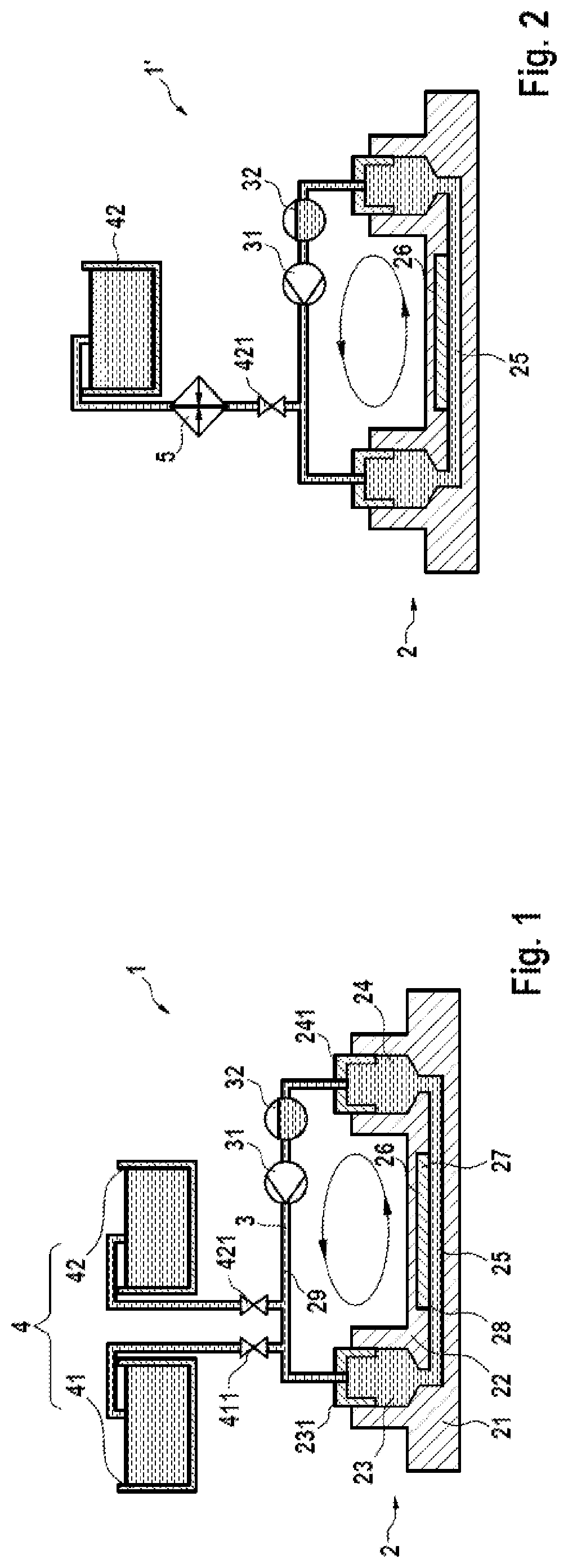
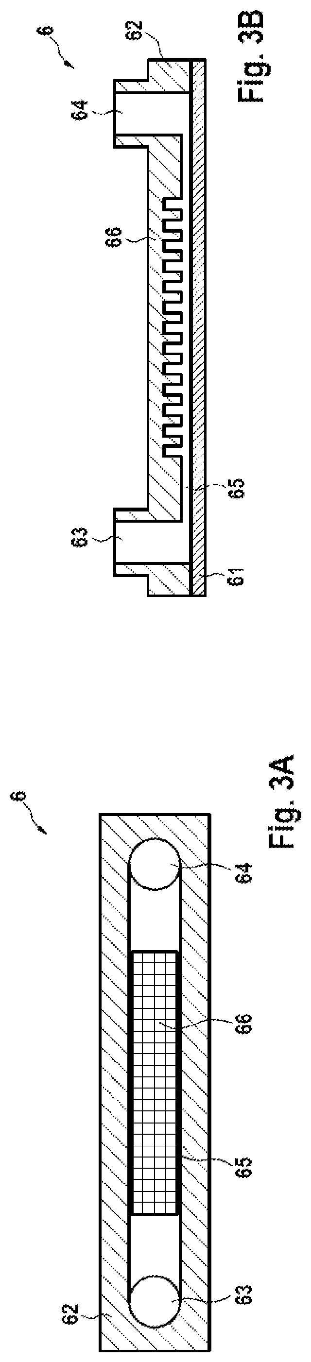
[0064]FIG. 1 shows a microfluidic system 1 for dPCR of a biological sample according to a first embodiment of the present disclosure in a schematic illustration, with the main components provided either in illustrative cross-section or as pictogram. The microfluidic system 1 as illustrated in FIG. 1 includes a microfluidic device 2 in the form of a microfluidic chip, the device 2 showing a similar structure as the state-of-the-art chip 7 depicted in FIG. 3B, wherein the device 2 substantially consists of a lower plate 21 and an upper plate 22, and provides an inlet 23, an outlet 24, and a flow channel 25 connecting the inlet 23 to the outlet 24. Furthermore, an array of reaction areas 26 in the form of microwells or nanowells is provided in the flow channel 25 at its upper side, i.e. at the inner side of the upper plate 22 in order to be able to monitor the reactions in the reaction areas 26 from above. Moreover, in the shown state, the microfluidic device 2 has already been flushed...


PUM


Abstract

A microfluidic system (1; 1′) for dPCR of a biological sample and a respective method is provided by the present disclosure, the system (1; 1′) comprising at least one microfluidic device (2) having an inlet (23), an outlet (24), a flow channel (25) connecting the inlet (23) to the outlet (24), and an array of reaction areas (26) in fluidic communication with the flow channel (25), a flow circuit (3) connectable to the microfluidic device (2), for flowing liquid through the flow channel (25) of the microfluidic device (2), a sample liquid source connectable to the microfluidic device (2), for providing the microfluidic device (2) with a sample liquid (27), a primary sealing liquid source connectable to the microfluidic device (2), for providing the microfluidic device (2) with initial sealing liquid (28) for sealing the sample liquid (27) inside the array of reaction areas (26), a secondary sealing liquid source (4) connectable to the microfluidic device (2), for providing the microfluidic device (2) with additional sealing liquid (29), and a pumping device (31) connected to the flow circuit (3) and adapted to pump said additional sealing liquid (29) through the flow channel (25).

Description

CROSS-REFERENCE TO RELATED APPLICATIONS[0001]This application claims the benefit and priority of European Application Serial No. 18189498.1, filed Aug. 17, 2018, which is incorporated herein by reference.TECHNICAL FIELD[0002]Generally, the present disclosure relates to the technical field of sample analysis, such as the assay of chemical or biochemical reactions, and more particular to the technical field of high throughput analysis of biological samples. In more detail, the present disclosure is directed to a microfluidic system for digital polymerase chain reaction (dPCR) of a biological sample. In further detail, such system comprises a microfluidic device with a flow channel in fluid communication with an array of reaction areas, also often referred to as partitions implemented as reaction chambers or reaction vessels, for example in the form of wells or microwells, which are functioning as reaction sites for chemical or biological reactions of at least one biological sample pro...

Claims


Application Information

Patent Timeline
Patent Type & Authority Applications(United States)
IPC IPC(8): B01L3/00
CPCB01L3/5027B01L2200/0689B01L2200/027B01L3/508B01L2300/0627B01J2219/00722B01L7/525B01L3/502723B01L2200/0684B01L2300/048B01L2300/0861B01L3/502715B01L3/502769B01L7/52B01L2300/0654B01L2300/185B01L2400/0487
Inventor STEINERT, CHRISZEDER, MICHAEL
Owner ROCHE MOLECULAR SYST INC
Why Eureka
Try Eureka