Magnetic field shaping components for magnetic field measurement systems and methods for making and using

a technology of magnetic field measurement and components, applied in the field of magnetic field measurement systems, can solve the problems of large maintenance costs, prohibitively expensive and bulky, etc., and achieve the effects of high magnetic permeability material, and reduced ambient background magnetic field

Active Publication Date: 2020-02-20
HI LLC
View PDF0 Cites 67 Cited by
  • Summary
  • Abstract
  • Description
  • Claims
  • Application Information

AI Technical Summary

Benefits of technology

[0007]In at least some embodiments, each of the at least one flux concentrator includes a first end and a second end opposite the first end, wherein the flux concentrator is tapered so that the first end has a larger surface area than the second end. In at least some embodiments, each of the at least one flux concentrator has a conical or pyramidal shape. In at least some embodiments, the conical or pyramidal shape is truncated at one end. In at least some embodiments, the high magnetic permeability material is selected from ferrite, Mu-metal, or any combination thereof.
[0008]In at least some embodiments, the at least one magnetometer includes a plurality of magnetometers and the at least one flux concentrator includes a plurality of flux concentrators. In at least some embodiments, each of the flux concentrators is configured to direct the concentrated or reoriented magnetic field signals to a different one of the magnetometers. In at least some embodiments, at least two of the magnetometers form a gradiometer. In at least some embodiments, one of the flux concentrators is configured to direct the concentrated or reoriented magnetic field signals toward at least one, but less than all, of the magnetometers of the gradiometer.
[0009]In at least some embodiments, the magnetic field measurement system further includes a passive shield disposed around the at least one magnetometer and configured to reduce an ambient background magnetic field at the at least one magnetometer. In at least some embodiments, the passive shield is made of a high magnetic permeability material. In at least some embodiments, the passive shield is formed in a shape of a helmet, hood, cap, or other shape conformable to a user's head.
[0010]In at least some embodiments, the magnetic f

Problems solved by technology

In this disclosure the OPM is primarily considered because the SQUID system requires cryogenic cooling, which is pro

Method used


Image

  • Magnetic field shaping components for magnetic field measurement systems and methods for making and using
  • Magnetic field shaping components for magnetic field measurement systems and methods for making and using
  • Magnetic field shaping components for magnetic field measurement systems and methods for making and using

Examples


Embodiment Construction

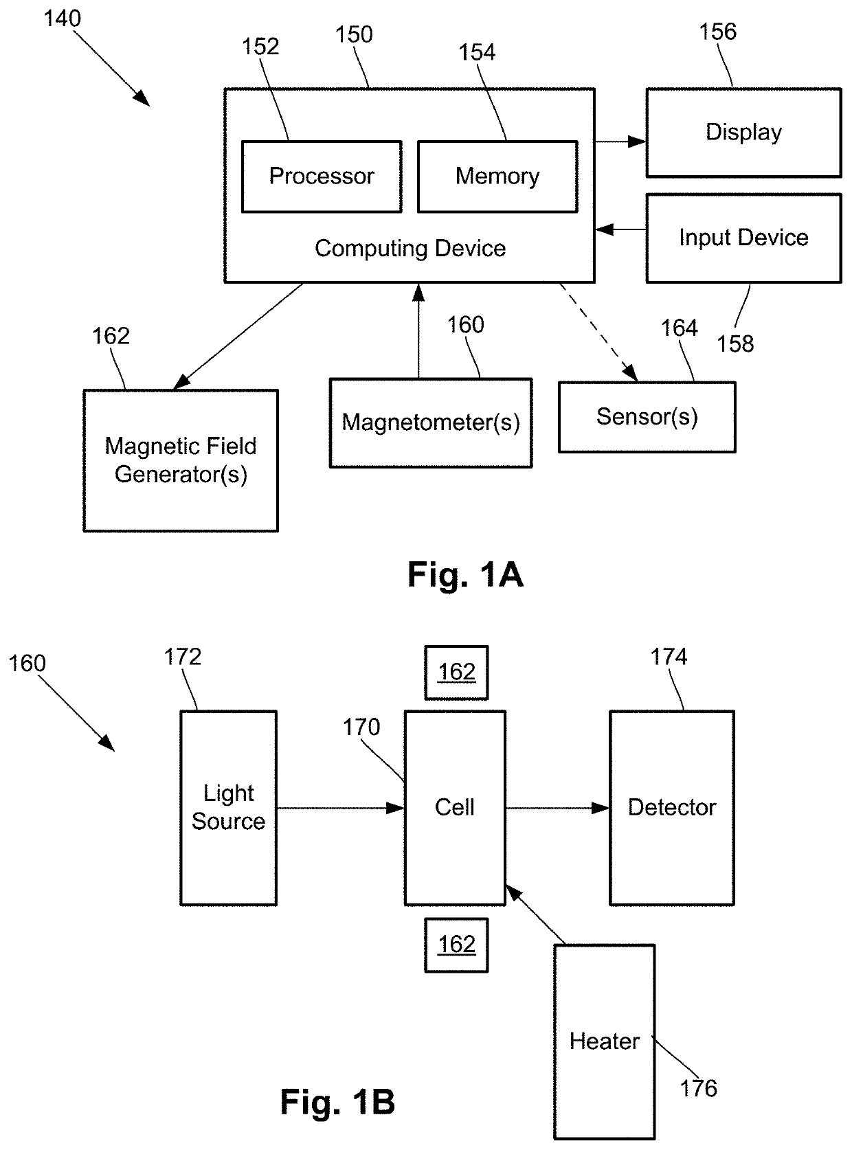
[0028]The present disclosure is directed to the area of magnetic field measurement systems using optically pumped magnetometers or other suitable magnetometers. The present disclosure is also directed to magnetic field measurement systems that include a magnetic field shaping component, such as a passive shield or flux concentrator, to facilitate measurements by an optically pumped magnetometer or other suitable magnetometers.

[0029]An optically pumped magnetometer (OPM) is a basic component used in optical magnetometry to measure magnetic fields. A magnetic field measurement system, as described herein, can include one or more (for example, an array of) optically pumped magnetometers, for example, one or more SERF zero-field vector magnetometers or scalar magnetometers. The magnetic field measurement system can be used to measure or observe electromagnetic signals generated by one or more sources (for example, biological sources). The system can measure biologically generated magnet...


PUM


Abstract

A magnetic field measurement system includes at least one magnetometer; and at least one flux concentrator made of a high magnetic permeability material and configured to receive magnetic field signals from a source, to concentrate the magnetic field signals or reorient the magnetic field signals in a preselected direction, and to direct the concentrated or reoriented magnetic field signals toward at least one of the at least one magnetometer. In addition to, or as an alternative to, the flux concentrator, the system can include a passive shield made of the high magnetic permeability material. The system may also include active shielding.

Description

CROSS-REFERENCE TO RELATED APPLICATIONS[0001]This application claims the benefit of U.S. Provisional Patent Application Ser. Nos. 62 / 719,928, filed Aug. 20, 2018, and 62 / 752,067, filed Oct. 29, 2018, both of which are incorporated herein by reference in their entireties.FIELD[0002]The present disclosure is directed to the area of magnetic field measurement systems using optically pumped magnetometers or other suitable magnetometers. The present disclosure is also directed to magnetic field measurement systems that include a magnetic field shaping component, such as a passive shield or flux concentrator, to facilitate measurements by an optically pumped magnetometer or other suitable magnetometers.BACKGROUND[0003]In the nervous system, neurons propagate signals via action potentials. These are brief electric currents which flow down the length of a neuron causing chemical transmitters to be released at a synapse. The time-varying electrical current within the neuron generates a magne...

Claims


Application Information

Patent Timeline
IPC IPC(8): G01R33/00G01R33/032
CPCG01R33/0011G01R33/0047G01R33/032G01R33/0017G01R33/26G01R33/0076G01R33/07G01R33/0029G01R33/0035G01R33/02G01R33/025G01R33/072G01R33/093
Inventor JIMÉNEZ-MARTÍNEZ, RICARDOALFORD, JAMUHENNINGER, MICHAEL
Owner HI LLC
Why Eureka
Try Eureka