Impedance matching device provided in high-frequency power system

a technology of impedance matching and power system, which is applied in the direction of electrical equipment, multiple-port networks, electric discharge tubes, etc., can solve problems such as inability to match plasma or misfire, and achieve the effect of improving the impedance mismatch immediately

Active Publication Date: 2020-03-26
THREE TEC CO LTD
View PDF0 Cites 1 Cited by
  • Summary
  • Abstract
  • Description
  • Claims
  • Application Information

AI Technical Summary

Benefits of technology

[0014]The present invention renders it possible to provide an impedance matching device capable of promptly improving an impedance mismatch between a high-frequency power source and a load even when the impedance of the load continuously changes.

Problems solved by technology

However, the conventional high-frequency power system 100 might not be able to improve an impedance mismatch caused by the impedance of the load 20 continuously changing after plasma ignition, resulting in unstable plasma or misfire.

Method used


Image

  • Impedance matching device provided in high-frequency power system
  • Impedance matching device provided in high-frequency power system
  • Impedance matching device provided in high-frequency power system

Examples


first embodiment

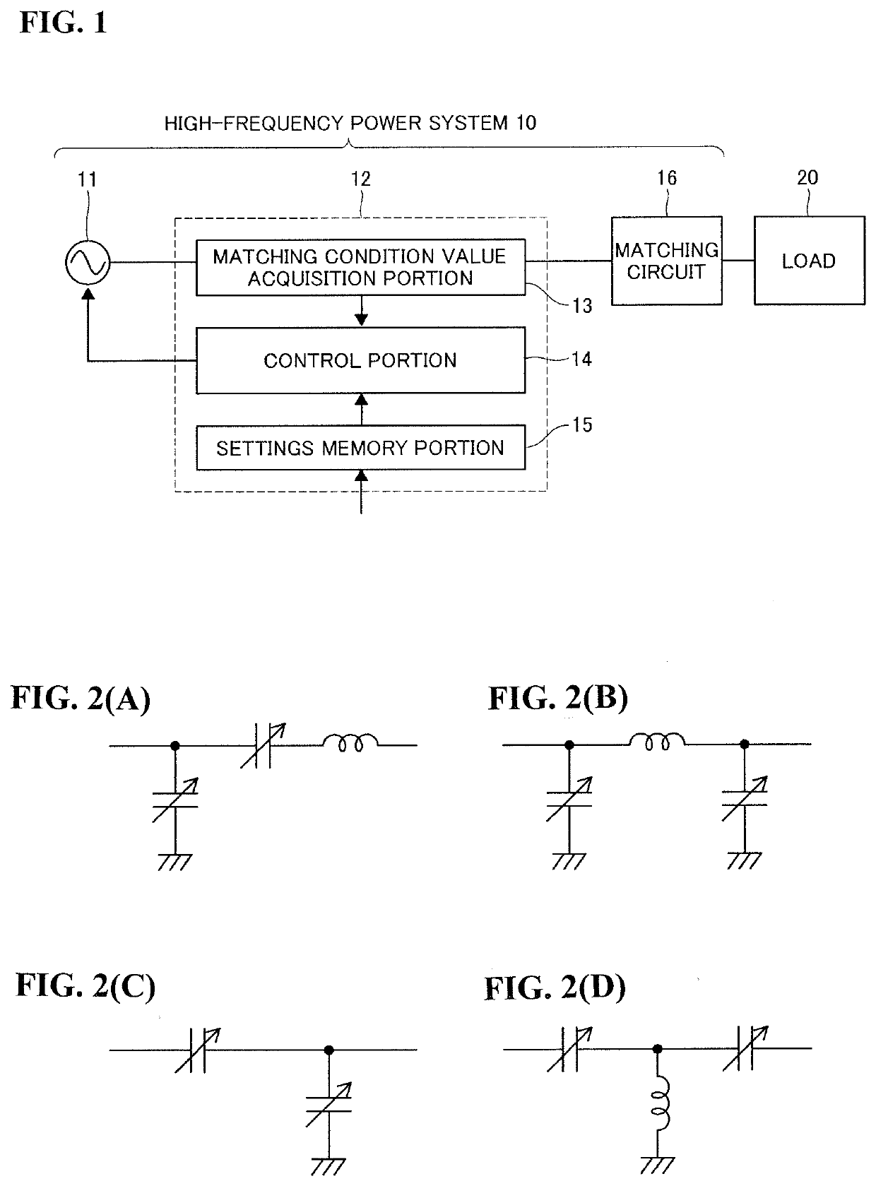
[0027]FIG. 1 illustrates a high-frequency power system 10 including an impedance matching device 12 according to a first embodiment of the present invention. The high-frequency power system 10 is intended for supplying a load 20 with necessary power, and further includes a high-frequency power source 11 and a matching circuit 16, as shown in the figure.

[0028]The high-frequency power source 11 outputs high-frequency power to the load 20 via the matching circuit 16. The high-frequency power source 11 is configured such that an oscillation frequency (i.e., a frequency of the high-frequency power) can be adjusted within a certain range (in the present embodiment, the range of ±1.00 MHz from 13.56 MHz at the center) in accordance with a command from the impedance matching device 12.

[0029]The matching circuit 16 includes two capacitors, each of which has a variable constant (capacitance), and one inductor, as shown in (A) of FIG. 2. The constants of the capacitors are changed by a matchin...

second embodiment

[0046]An impedance matching device 12 according to a second embodiment of the present invention includes a matching condition value acquisition portion 13, a control portion 14, and a settings memory portion 15, as in the first embodiment. However, in the present embodiment, the control portion 14 is operated differently from the first embodiment. An operation example of the control portion 14 in the second embodiment will be described below with reference to FIGS. 9 and 10.

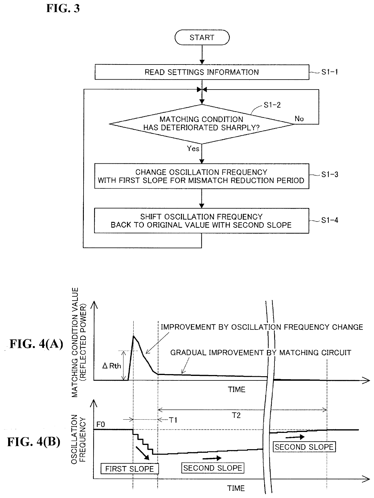
[0047]Initially, the control portion 14 reads settings information memorized in the settings memory portion 15 (step S2-1). The settings information is related to a first slope, a second slope, a mismatch reduction period, and a threshold.

[0048]Next, the control portion 14 determines whether the matching condition has deteriorated sharply (step S2-2), as in step S1-2 of the first embodiment. The control portion 14 repeats step S2-2 every 100 μs until the matching condition deteriorates sharply.

[0049]Once the matc...


PUM


Abstract

Provided is an impedance matching device capable of promptly improving an impedance mismatch between a high-frequency power source and a load even when the impedance of the load continuously changes.
An impedance matching device according to the present invention is for use in a high-frequency power system configured to supply a load with an output from a high-frequency power source via a matching circuit whose constant is mechanically changed, and the impedance matching device includes a matching condition value acquisition portion for acquiring a matching condition value indicating a matching condition between the high-frequency power source and a load, and a control portion for controlling an oscillation frequency of the high-frequency power source based on the matching condition value. When the matching condition value indicates deterioration of the matching condition, the control portion changes the oscillation frequency with a first slope toward improving the matching condition, and thereafter shifts the oscillation frequency back to an original value with a second slope more gradual than the first slope.

Description

TECHNICAL FIELD[0001]The present invention relates to an impedance matching device for use in a high-frequency power system configured to supply a load with an output from a high-frequency power source via a matching circuit whose constant is mechanically changed.BACKGROUND ART[0002]Semiconductor manufacturing processes, such as etching and thin-film formation, use a plasma treatment device and a high-frequency power system for supplying the plasma treatment device with necessary power. The high-frequency power system normally has the function of achieving an impedance match with the plasma treatment device in order to stably and efficiently supply the plasma treatment device with power.[0003]Patent Document 1 discloses a high-frequency power system 100 with an impedance matching function, including a high-frequency power source 101, an impedance matching device 102, and a matching circuit 103 (see FIG. 11). The impedance matching device 102 is configured to change an oscillation fr...

Claims


Application Information

Patent Timeline
Patent Type & Authority Applications(United States)
IPC IPC(8): H01J37/32H03H7/38
CPCH03H7/38H01J2237/327H01J37/32183H01J37/32155H01J37/3299H03H7/40H03H11/28H03H7/345
Inventor TAKAHARA, TOSHIHIROKAWATA, ETSUROKISHIRA, TAKAMICHIOKAZAKI, TAKEHIROFUJIWARA, NOBUTAKAKATSUYA, ATSUSHINAKAMURA, KENTA
Owner THREE TEC CO LTD
Why Eureka
Try Eureka