Eureka AIR delivers breakthrough ideas for toughest innovation challenges, trusted by R&D personnel around the world.

Mpedance matching device provided in high frequency power system

A technology of impedance matching and high-frequency power supply, which is applied in the direction of impedance matching network, impedance network, circuit, etc., can solve the problems of plasma instability, inability to improve impedance mismatch, fire, etc., and achieve the effect of improving impedance mismatch

Active Publication Date: 2020-03-31
THREE TEC CO LTD
View PDF6 Cites 0 Cited by
  • Summary
  • Abstract
  • Description
  • Claims
  • Application Information

AI Technical Summary

Problems solved by technology

[0006] However, if the high-frequency power supply system 100 in the prior art described above continuously changes the impedance of the load 20 after the plasma is ignited, the resulting impedance mismatch cannot be improved. As a result, the plasma may become unstable or fire situation

Method used


Image

  • Mpedance matching device provided in high frequency power system
  • Mpedance matching device provided in high frequency power system
  • Mpedance matching device provided in high frequency power system

Examples


no. 1 example

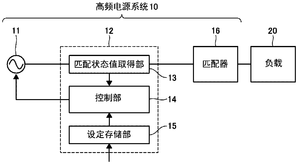
[0031] figure 1 A high-frequency power supply system 10 including the impedance matching device 12 according to the first embodiment of the present invention is shown. The high-frequency power supply system 10 is used to supply the required power to the load 20, such as figure 1 As shown, a high frequency power supply 11 and a matching unit 16 are also included.

[0032] The high-frequency power supply 11 outputs high-frequency power to the load 20 via the matching unit 16 . The high-frequency power supply 11 is configured to be able to adjust the oscillation frequency (that is, the high-frequency power frequency).

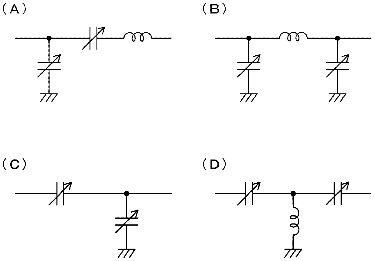
[0033] Such as figure 2 As shown in (A), the matching unit 16 includes two capacitors and one inductor whose constant (capacitance) can be changed. The constant of the capacitor is changed by a matching state detection unit and a control unit (not shown) included in the matching unit 16 so as to improve the impedance mismatch between the high-frequency pow...

no. 2 example

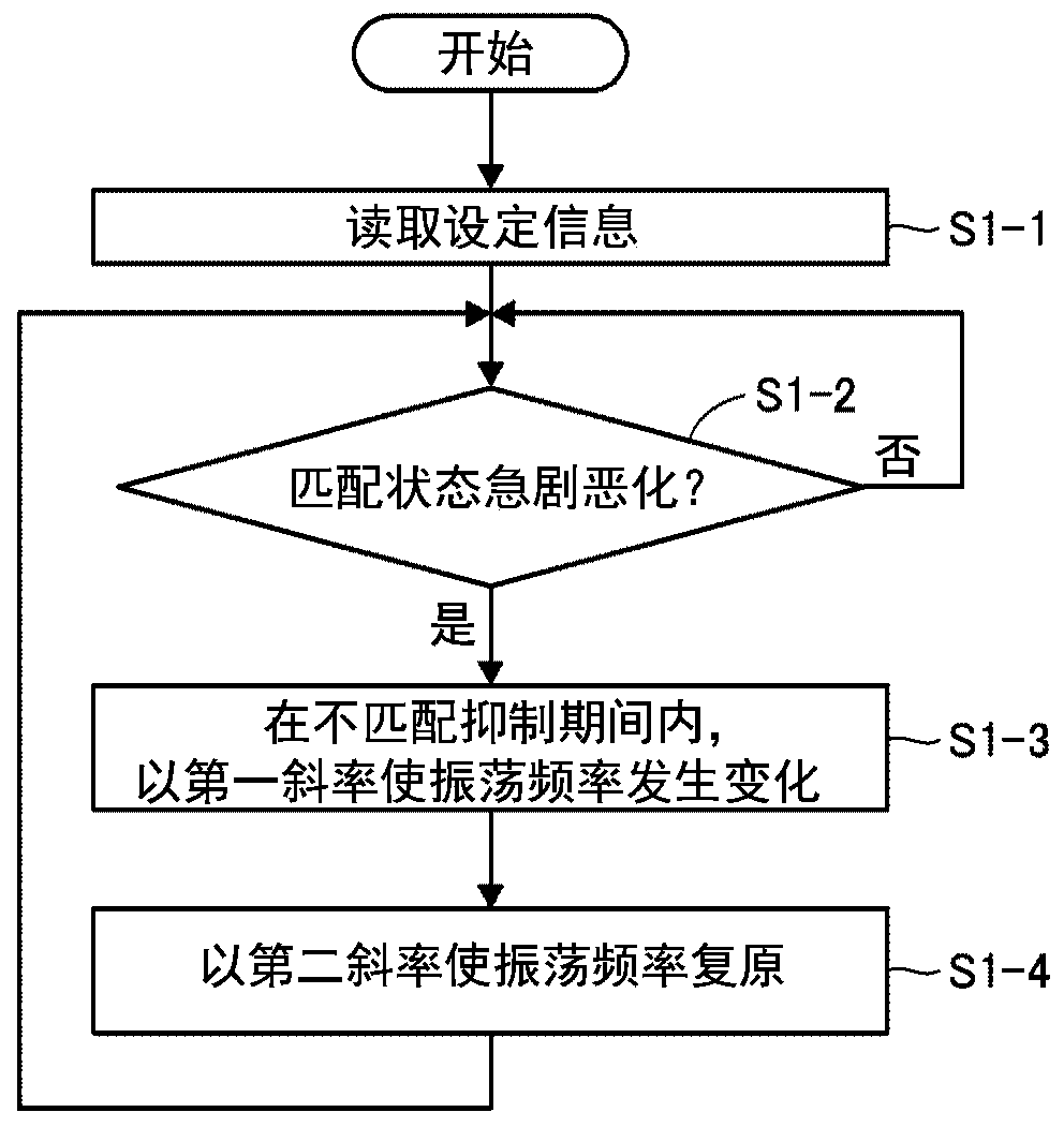
[0051] The impedance matching device 12 according to the second embodiment of the present invention includes a matching state value acquisition unit 13 , a control unit 14 , and a setting storage unit 15 similarly to the first embodiment. However, the control unit 14 in this embodiment operates differently from the control unit in the first embodiment. Below, refer to Figure 9 as well as Figure 10 , an example of the operation of the control unit 14 of the second embodiment will be described.

[0052] First, the control unit 14 reads the setting information stored in the setting storage unit 15 (step S2-1). The setting information includes a first slope, a second slope, a mismatch suppression period, and a threshold.

[0053] Next, the control unit 14 judges whether or not the matching state has deteriorated rapidly in the same manner as step S1-2 of the first embodiment (step S2-2). The control unit 14 repeatedly executes step S2-2 every 100 μs until the matching state ...


PUM


Abstract

An impedance matching device is provided, which can improve impedance mismatching between a high-frequency power supply and a load even when the impedance of the load continuously changes. The impedance matching device according to the present invention is for use in a high-frequency power system configured to supply a load with an output from a high-frequency power source via a matching circuit whose constant is mechanically changed, and the impedance matching device includes a matching condition value acquisition portion for acquiring a matching condition value indicating a matching condition between the high-frequency power source and a load, and a control portion for controlling an oscillation frequency of the high-frequency power source based on the matching condition value. When thematching condition value indicates deterioration of the matching condition, the control portion changes the oscillation frequency with a first slope toward improving the matching condition, and thereafter shifts the oscillation frequency back to an original value with a second slope more gradual than the first slope.

Description

technical field [0001] The present invention relates to an impedance matching device provided in a high-frequency power supply system configured to supply an output of a high-frequency power supply to a load via a matching device that mechanically changes a constant. Background technique [0002] In semiconductor manufacturing processes such as etching and thin film formation, a plasma processing apparatus and a high-frequency power supply system for supplying required power to the plasma processing apparatus are used. Generally, the high-frequency power supply system has a function of matching the impedance of the plasma processing apparatus in order to stably and efficiently supply power to the plasma processing apparatus. [0003] Patent Document 1 discloses a high-frequency power supply system 100 having an impedance matching function including a high-frequency power supply 101, an impedance matching device 102, and a matching device 103 (see Figure 11 ). The impedance...

Claims


Application Information

Patent Timeline
Patent Type & Authority Applications(China)
IPC IPC(8): H01J37/32H03H7/38
CPCH01J37/32155H01J37/32183H01J37/3299H03H7/38H03H7/40H03H11/28H03H7/345H01J2237/327
Inventor 高原敏浩河田悦郎岸良贵通冈崎丈浩藤原延崇胜冶笃史中村谦太
Owner THREE TEC CO LTD
Why Eureka
Eureka Blog
Learn More