Resistance welding copper terminals through mylar

a technology of resistance welding and copper terminals, applied in the direction of fixed connections, heater elements, manufacturing tools, etc., can solve the problems of reworking of bad welds, sometimes breaking of welds, etc., and achieve the effect of reliable electrical connections

Active Publication Date: 2020-03-26
CALIENTE LLC
View PDF0 Cites 1 Cited by
  • Summary
  • Abstract
  • Description
  • Claims
  • Application Information

AI Technical Summary

Benefits of technology

[0009]An advantage of the present invention is that a reliable electrical connection is established through an inert substrate.
[0010]Another advantage is that the circuit formed provides a terminal to which various wire sizes can be coupled.

Problems solved by technology

Additionally, when parts that have rigid leads are welded directly to a thick film pad the welds can sometimes break if the lead is flexed in certain ways.
This results in a bad weld which will have to be reworked or the part scrapped.

Method used


Image

  • Resistance welding copper terminals through mylar
  • Resistance welding copper terminals through mylar
  • Resistance welding copper terminals through mylar

Examples


Embodiment Construction

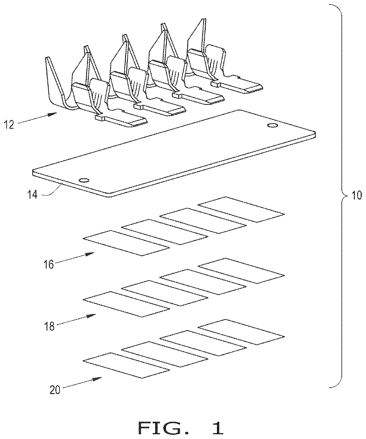
[0023]Referring now to the drawings, and more particularly to FIG. 1, there is shown, an exploded perspective view of elements that form an electrical transitional assembly 10 which generally includes electrical conductors 12 in the form of terminals 12, a layer of an electrically inert substrate 14, electrically conductive films 16, electrically conductive adhesive 18, and electrically conductive tape 20. The electrically conductive films 16 are applied to electrically inert substrate 14 by a method such as screen printing of a conductive ink. To the electrically conductive films 16 the electrically conductive tape 20, which has the electrically conductive adhesive 18 on one side of tape 20, is applied to films 16. Electrically inert substrate 12 may be in the form of a sheet of mylar 12. Tape 20 and adhesive 18 may be integrally formed before application to film 16. It is also contemplated that adhesive 18 and tape 20 are applied to film 16 individually. It is further contemplated...


PUM

PropertyMeasurementUnit
energyaaaaaaaaaa
energyaaaaaaaaaa
energyaaaaaaaaaa

Abstract

A method for fusing an electrical conductor to a film pad circuit including the steps of: providing an electrically inert substrate having a first surface and an opposing second surface; applying an electrically conductive film to the second surface of the electrically inert substrate; applying an electrically conductive member to the electrically conductive film; placing an electrical conductor on the first surface of the electrically inert substrate; and fusing the electrical conductor to the conductive member.

Description

CROSS REFERENCE TO RELATED APPLICATIONS[0001]This is a non-provisional application based upon U.S. provisional patent application Ser. No. 62 / 736,141, entitled “ RESISTANCE WELDING COPPER TERMINALS THROUGH MYLAR”, filed Sep. 25, 2018, which is incorporated herein by reference.BACKGROUND OF THE INVENTION1. Field of the Invention[0002]The present invention relates to electrical resistance welding, and, more particularly, to the resistance welding of copper terminals through a layer of mylar.2. Description of the Related Art[0003]Resistant welding generally refers to welding processes such as spot and seam welding that produce a coalescence of surfaces where the heat generated to form the weld is generated by the electrical resistance of the material being welded along with the time and the force used to hold the materials together during the welding process. Some factors that influence the required welding temperatures are the proportions of the workpieces, whether there is metal coat...

Claims


Application Information

Patent Timeline
Patent Type & Authority Applications(United States)
IPC IPC(8): H01R43/02H01R4/02H01R4/18H01R12/51B23K11/00B23K11/16B23K11/18H05B3/03
CPCH01R43/0214H05B3/03B23K11/163H01R4/185H01R4/029B23K11/002B23K11/18H01R12/515H01R4/04H01R12/65H05B3/06H05B3/267H05B2203/003H05B2203/013
Inventor BLAKE, JAMES T.AMBRIOLE, TYLER W.GRAY, SAMUEL N.
Owner CALIENTE LLC
Why Eureka
Try Eureka