
Material transportation system, transportation method and storage apparatus

Active Publication Date: 2020-04-16
SHANGHAI FORTREND TECH CO LTD
View PDF0 Cites 7 Cited by
  • Summary
  • Abstract
  • Description
  • Claims
  • Application Information

AI Technical Summary

Benefits of technology

The present invention provides a material transportation system, a method, and an apparatus that can simultaneously transport multiple material boxes between different locations, using a movable storage rack and an automatic transportation apparatus. This system overcomes the limitations of existing OHT systems and reduces design complexity, making it easier to adjust and apply in different production lines. The automatic lifting translation mechanism and the top correction positioning components ensure accurate positioning of the movable storage rack, preventing tilting and tipping over during the transportation process. This results in an improved practical application range for the material transportation system.

Problems solved by technology

However, although the fully-automatic overhead traveling crane track system is mature in technology and is the standard configuration of the current semiconductor wafer factory, the traditional OHT system also has serious and insurmountable defects as follows: first of all, due to the high-speed running of the material boxes in the OHT system, from the perspective of safety, the traditional OHT system generally adopts the one-way transportation design to prevent the serious collision accident caused by faults in control or mechanical failures.
Undoubtedly, the initial design cost is greatly increased.
Moreover, for the wafer factory, once the production line is expanded, the process equipment is adjusted or the layout of the production line is re-optimized, the traditional OHT system will be difficult and expensive to modify, which will further severely limit the enterprise decision.
Moreover, in the traditional OHT system, the vertical lifting suspender mechanism picks and places the material boxes in a vertical lifting way, the vertical suspender is required to be aligned to a wafer box or the wafer box is required to be aligned to the workstation, resulting in strict requirements for the position accuracy of the workstation of the devices, so that the optional change of the position is not allowed; and therefore, in the traditional OHT system, the flexible updating of a local process or the device is limited, which results in the shortage of flexibility for updating the local process or device.
Secondly, since the traditional OHT system runs in one way, once a single-point failure occurs and cannot be solved for a long time, the serious traffic congestion will happen, resulting in sharp decrease of the transportation efficiency of the entire OHT system, thereby affecting the production of the entire wafer factory.
Furthermore, since the designed carrying capacity of the single-box track overhead traveling crane in the OHT system is determined at the initial stage of the factory construction, when the technology is updated later and especially when the size and weight of the material box are changed, the OHT system must be upgraded synchronously, the OHT system is high in cost, has high requirement for the maintenance technology and is also high in daily maintenance expense, which consequently leads to the violent cost increment and time waste.
Therefore, the flexibility in updating the OHT system is limited.
Finally, in the traditional OHT system, the single-box track overhead traveling crane is not suitable for transporting the heavy-weight and large-size material boxes, which further severely limits the application range of the traditional OHT system.
Therefore, the traditional OHT system is severely limited in the practical production and applications.

Method used

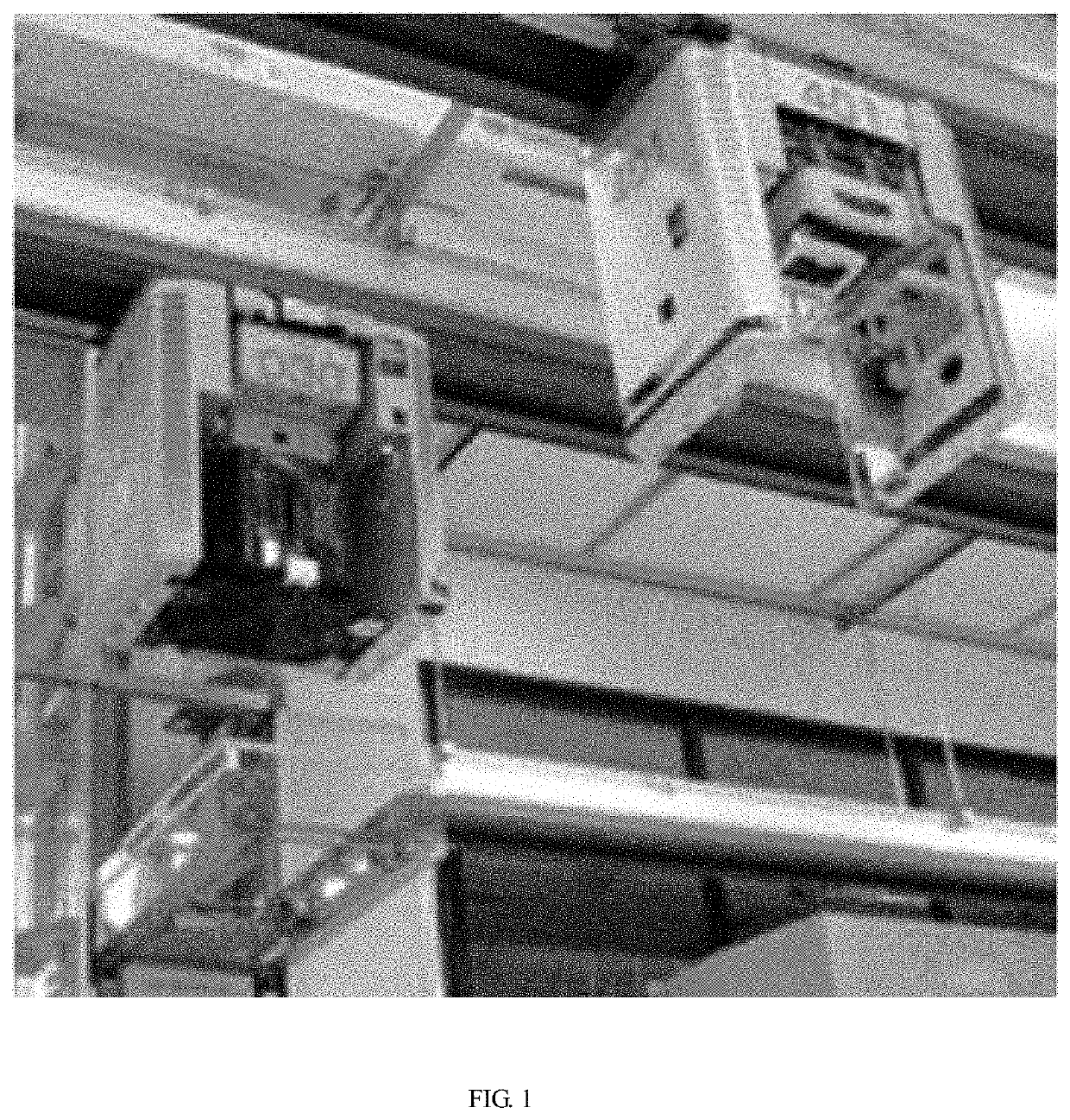
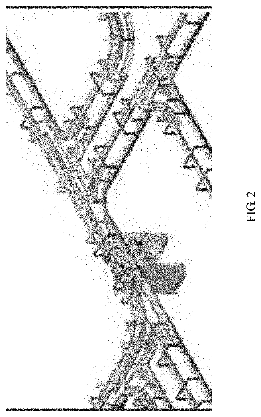
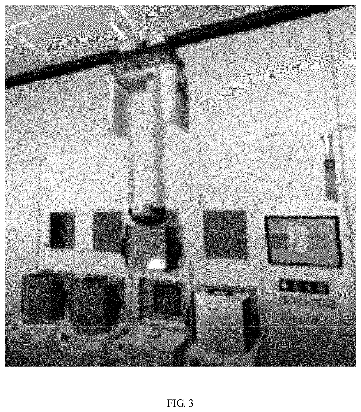

Image

  • Material transportation system, transportation method and storage apparatus
  • Material transportation system, transportation method and storage apparatus
  • Material transportation system, transportation method and storage apparatus

Examples


Embodiment Construction

[0162]In order to make the content of the present invention clearer and easier to understand, the content of the present invention will be further described below in conjunction with the drawings of description. Of course, the present invention is not limited to the specific embodiment, and the general replacements well known to those skilled in the art shall be covered within the protection scope of the present invention.

[0163]The present invention is further described below in combination with FIG. 4 to FIG. 18 and specific embodiments. It should be noted that the drawings are in a very simplified form according to a non-precise ratio, and are only used to conveniently and clearly achieve the purpose of describing the objectives of the present embodiment.

[0164]Referring to FIG. 4, a material storage apparatus 00 of the present embodiment is arranged on an abutment 100; the abutment 100 is hollowed and configured for isolating the material storage apparatus 00 from the floor, there...


PUM


Abstract

The present invention provides a material transportation system, a material transportation method and a material storage apparatus. The material storage apparatus is provided with a movable storage rack, wherein the movable storage rack is configured for carrying a plurality of material boxes and can be separated from the material storage apparatus; and an automatic transportation apparatus can move freely along any route in any direction, wherein the automatic transportation apparatus is configured for carrying the movable storage rack. Moreover, the movable storage rack is sent to be in front of the material storage apparatus or transported from the material storage apparatus to a target storage position. The present invention simultaneously transports a plurality of material boxes between the material storage apparatuses and between the material storage apparatus and the processing equipment. By adopting the automatic transportation apparatus, the single-box track overhead traveling crane and the overhead track in the traditional OHT system are canceled, so that the problems that the traditional OHT system is high in design complexity, highly difficult and limited in later adjustment, and limited in the practical application can be overcome.

Description

CROSS-REFERENCE TO RELATED APPLICATION[0001]This application claims the priority benefit of China application serial no. 201811191242.8, filed on Oct. 12, 2018. The entirety of the above-mentioned patent application is hereby incorporated by reference herein and made a part of this specification.TECHNICAL FIELD[0002]The present invention relates to the technical field of semiconductor devices, and more particularly relates to a material storage apparatus, a material transportation system and a material transportation method.BACKGROUND ART[0003]In a production workshop pursuing high efficiency, the factory is generally divided into several production areas according to factors such as the production process of products, the environment requirements, the factory affairs requirements and the like. In the production process, semi-finished products must flow among different production areas in a crossing manner. In order to improve the production efficiency and the production stability, ...

Claims


Application Information

Patent Timeline
IPC IPC(8): B65G1/137B65G1/04
CPCB65G1/1373B65G1/0464H01L21/67703H01L21/6773H01L21/67736B65G35/00B65G2201/0214B65G2201/0297B65G1/04B65G1/0492B65G1/0471H01L21/67769H01L21/67733H01L21/67259
Inventor WU, KUNG
Owner SHANGHAI FORTREND TECH CO LTD
Learn More