Method And Control Unit For Compensation Of Eddy Current Induced Magnetic Fields In Magnetic Resonance Imaging

a magnetic resonance imaging and control unit technology, applied in the field of methods and control units for compensating eddy current induced magnetic fields in magnetic resonance imaging systems, can solve problems such as difficult to easily compensate, additional magnetic field is a problem for image quality, and disturb the image quality of magnetic resonance measurements, etc., to achieve the effect of facilitating the reduction and/or compensation of eddy current induced magnetic fields

Pending Publication Date: 2020-04-16
SIEMENS HEALTHCARE GMBH
View PDF6 Cites 4 Cited by
  • Summary
  • Abstract
  • Description
  • Claims
  • Application Information

AI Technical Summary

Benefits of technology

[0014]MRI devices and methods are improved to facilitate a reduction and/or compensa

Problems solved by technology

In the technical field of magnetic resonance imaging (MRI), there occurs the problem that magnetic fields generated by eddy currents can disturb the image quality of magnetic resonance (MR) measurements.
Specifically, the formation of non-linear field disturbances generated by eddy currents, i.e. of “higher spatial orders”, causes problems that cannot be easily compensated.
Since MR imaging strongly depends on well-controlled magnetic fields (i.e. the homogeneity of the B0 field and the linearity of the gradient field), any additional magnetic field is a problem for image quality.
For example, they can result in image distortion, signal loss or insufficient fat saturation.
Both cases are problematic for clinical imaging with fat saturation because the signal from water can disappear and the signal from fat can be maintained.
Especially local incidents may possibly be misinterpreted as pathologies, since fat saturation basically works and

Method used


Image

  • Method And Control Unit For Compensation Of Eddy Current Induced Magnetic Fields In Magnetic Resonance Imaging
  • Method And Control Unit For Compensation Of Eddy Current Induced Magnetic Fields In Magnetic Resonance Imaging
  • Method And Control Unit For Compensation Of Eddy Current Induced Magnetic Fields In Magnetic Resonance Imaging

Examples


Embodiment Construction

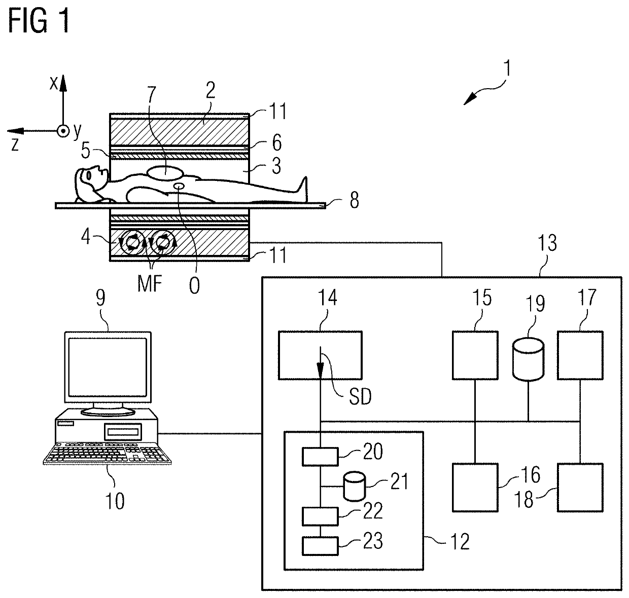
[0090]FIG. 1 shows a schematic representation of a magnetic resonance imaging system 1 (“MRI-system”). The MRI system 1 includes the actual magnetic resonance scanner (data acquisition unit) 2 with an examination space 3 or patient tunnel in which a patient or test person is positioned on a driven bed 8, in whose body the actual examination object O is located.

[0091]The magnetic resonance scanner 2 is typically equipped with a basic field magnet system or B0 coil 4, a gradient system or gradient coils 6 as well as an RF transmission antenna system or whole body coil 5 and an RF reception antenna system or local coils 7. In the shown exemplary embodiment, the RF transmission antenna system 5 is a whole-body coil permanently installed in the magnetic resonance scanner 2, in contrast to which the RF reception antenna system 7 is formed as local coils (symbolized here by only a single local coil) to be arranged on the patient or test subject. In principle, however, the whole-body coil c...


PUM


Abstract

Eddy current induced magnetic fields (MF) are compensated in a magnetic resonance imaging system. An MR-sequence (M) includes a number of gradients. A dataset includes values of an amplitude and a time constant of eddy current fields of a number of gradients on at least one gradient axis. A number of points in time within the time period of the MR-sequence are defined. A number of constant currents are calculated for a number of coils of the magnetic resonance imaging system based on the dataset. The number of constant currents is designed to compensate at least at the one defined point in time (PT1, PT2). The calculated number of constant currents are applied on the related coils prior or during the application of the MR-sequence or a section of the MR-sequence.

Description

RELATED CASE[0001]This application claims the benefit of EP 18200639.5, filed on Oct. 16, 2018, which is hereby incorporated by reference in its entirety.FIELD[0002]The present embodiments describe a method and a control unit for compensation of eddy current induced magnetic fields in a magnetic resonance imaging system, as well as a related magnetic resonance imaging system.BACKGROUND[0003]In the technical field of magnetic resonance imaging (MRI), there occurs the problem that magnetic fields generated by eddy currents can disturb the image quality of magnetic resonance (MR) measurements. Various methods address eddy currents as disclosed for instance in DE 102010035539 B4, U.S. Pat. No. 7,633,292 B2, and US 20180011160 A1.[0004]Specifically, the formation of non-linear field disturbances generated by eddy currents, i.e. of “higher spatial orders”, causes problems that cannot be easily compensated.[0005]Eddy currents can be generated in MRI devices by temporal changes of magnetic ...

Claims


Application Information

Patent Timeline
IPC IPC(8): G01R33/385G01R33/44
CPCG01R33/446A61B5/055G01R33/385G01R33/56G01R33/3875G01R33/56518
Inventor HÖLSCHER, UVOKÖHLER, MICHAELNIEDERLÖHNER, DANIELSTEMMER, ALTO
Owner SIEMENS HEALTHCARE GMBH
Why Eureka
Try Eureka