
Method and device for optimizing the use of emitter and detector in an active remote sensing application

a technology of active remote sensing and emitter, applied in the direction of instruments, wave based measurement systems, etc., can solve the problems of technical limitations, physical maximum transmission or minimum detection power, etc., and achieve the effect of optimizing the available optical budg

Active Publication Date: 2020-04-16
FASTREE3D
View PDF5 Cites 16 Cited by
  • Summary
  • Abstract
  • Description
  • Claims
  • Application Information

AI Technical Summary

Benefits of technology

The present invention aims to provide a method for arranging a laser emitter and a photo-sensitive detector to optimize the available optical budget for eye-safety, signal-to-background ratio, and power consumption of the detector when working in a remote sensing configuration. A device implementing this method is also provided.

Problems solved by technology

Devices used for remote sensing typically face challenges posed by environmental conditions, technical limitations, and juristic regulations.
Environmental challenges could be, for example, temperature or sun irradiation.
Technical limitations could be related to the physical maximum transmission or minimum detection power.
Second, each receiver comes with a certain threshold of noise equivalent power.
The sensitivity of the receiver is ultimately limited by the laws of physics.
For example, if one works with light, if the remote sensing application uses a receiver sensitive to single photons, this sensitivity cannot be improved much further.
Likewise, the emitted power cannot be increased at will either.
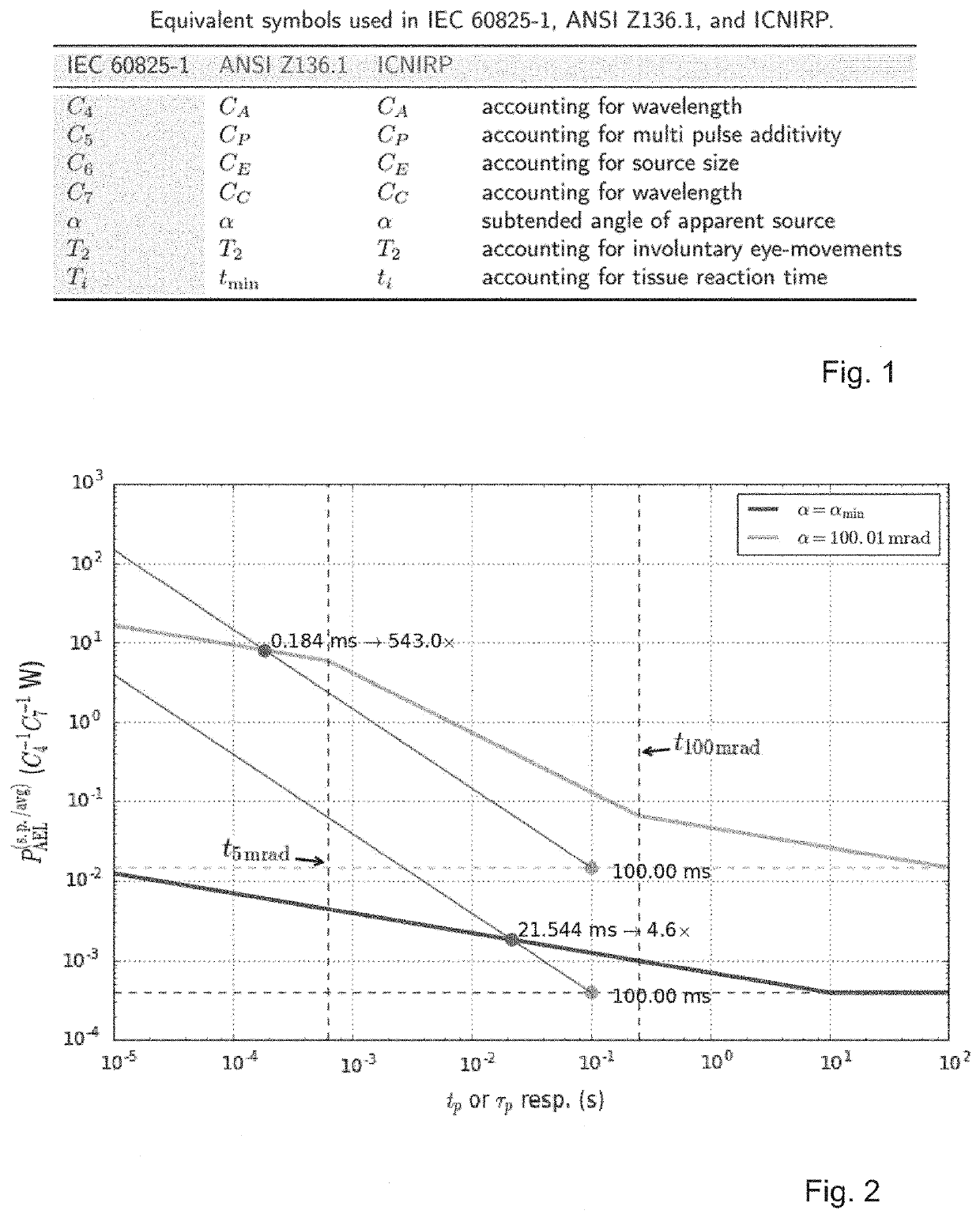
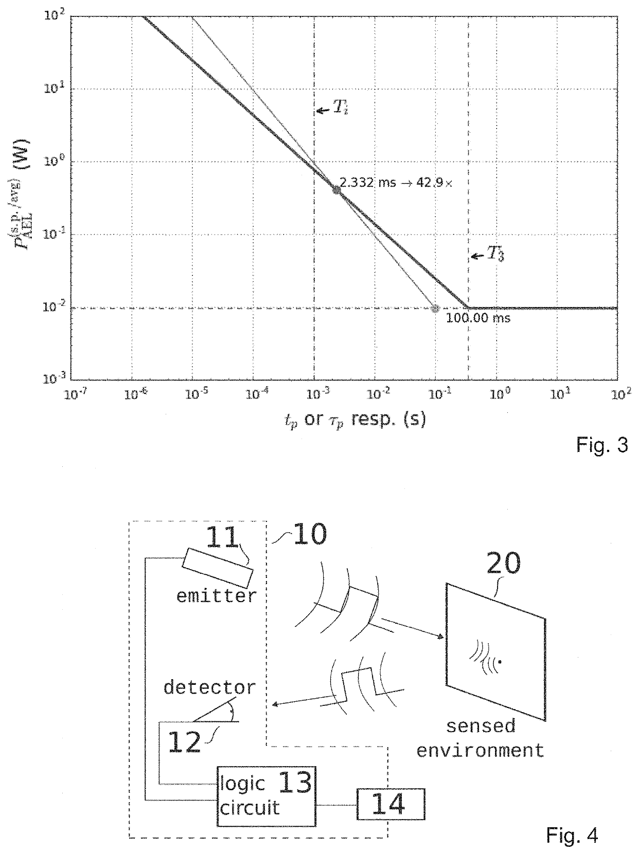
A laser used for remote sensing is typically limited to much lower limits: they're typically purposed to be used among humans, who in many use cases aren't equipped with personal safety accessories.
This can lead to a permitted exposure limit orders of magnitude higher than the limit given for the retinal hazard region.
For a safety analysis one has to always consider the most hazardous and / or restrictive position, which often means a situation such that the subtended angle is smallest.
Collimated lasers typically need to be considered as small sources: even if the source is extended from close by, since the power density in a collimated beam doesn't diminish over distance, larger distances result in equal accessible power with smaller subtended angles, and thus represent a more hazardous situation.
Such a system has the disadvantage that the allowed emission limit of the two sources combined need to be below the regulated limit, such that the eventual power increase is rather low.
Besides, such a system would need additional safety features to ensure the invisible light doesn't emit if the visible source is out of order, for example; which adds cost and complexity.
In many applications these trade-offs are not realistic.
A large diameter collimated beam requires a condenser lens of at least the same diameter, which leads to a large and bulky over-all system.
Beside the strategies highlighted in the prior art, a mere increase in sensitivity or emission power is often not feasible.
If this algorithm ends up using the wrong model, for example a black body radiation instead of another laser, their proposed method may fail to converge to a solution.
This in turn implies a relatively strong laser, and / or it means that the performance of the method overall is limited by the signal to background ratio (SBR) present in the P-image alone.
However, if we take the variance as an indicator of the noise components in the resulting image, the signal to noise ratio (SNR) actually worsens.
In many cases this is undesirable.
Such active and external measures typically increase cost and complexity of the end device.
This type of solution brings in design constraints which in some cases cannot be balanced with more fundamental design requirements.

Method used


Image

  • Method and device for optimizing the use of emitter and detector in an active remote sensing application
  • Method and device for optimizing the use of emitter and detector in an active remote sensing application
  • Method and device for optimizing the use of emitter and detector in an active remote sensing application

Examples


Embodiment Construction

[0078]The present invention will be described with respect to particular embodiments and with reference to certain drawings. The invention is not limited thereto but only by the claims. The drawings described are only schematic and are non-limiting. In the drawings, the size of some of the elements may be exaggerated and not drawn on scale for illustrative purposes. The dimensions and the relative dimensions do not necessarily correspond to actual reductions to practice of the invention.

[0079]Furthermore, the terms first, second, third and the like in the description and in the claims, are used for distinguishing between similar elements and not necessarily for describing a sequential or chronological order. The terms are interchangeable under appropriate circumstances and the embodiments of the invention can operate in other sequences than described or illustrated herein.

[0080]Moreover, the terms top, bottom, over, under and the like in the description and the claims are used for d...


PUM

PropertyMeasurementUnit
emission with wavelengthaaaaaaaaaa
wavelength rangeaaaaaaaaaa
time unit integration timeaaaaaaaaaa

Abstract

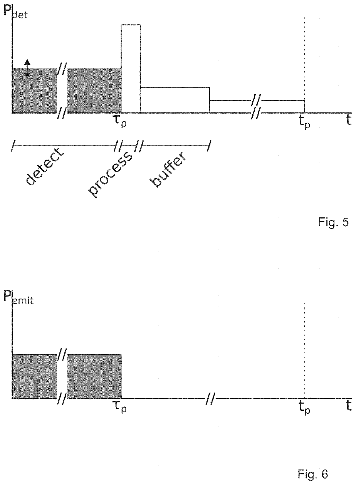
The invention relates to a method of an optimal arrangement in time of a laser emitter and a detector for a remote sensing application, comprising: —setting a target time unit integration time tp; —translating said time unit integration time into a reduced time τp and its corresponding power increase factor η−1; —activating both the laser emitter, with a power output corrected by η−1, and the detector for a duration of τp; —deactivating the emitter and detector after duration τp; —keep emitter and detector off for the subsequent duration toff=tp−τp.The invention further relates to a device implementing said method.

Description

TECHNICAL FIELD[0001]The present invention relates to a method and a device for optimizing the use of emitter and detector in an active remote sensing application. More specifically, the present invention optimizes said use of emitter and detector with regard to eye-safety of the used laser emitter, the signal to background ratio in the detection, and the power consumption of the detector.PRIOR ART[0002]Remote sensing refers to a method to acquire information about certain properties of a target under investigation, without being in physical contact with said target. There are active and passive methods.[0003]Passive methods could for example involve to analyze satellite photographs, and to infer on the topography of the landscape from said photographs, or to deduce the electricity use of a certain region based on the light pollution captured in night photographs. These examples are of passive nature as the satellite doesn't actively irradiate the target. Instead, it uses the light ...

Claims


Application Information

Patent Timeline
Patent Type & Authority Applications(United States)
IPC IPC(8): G01S7/484G01S7/486G01S7/48
CPCG01S7/4808G01S7/4868G01S7/484G01S7/48
Inventor KELLER, STEFAN THOMASPENLAE, BRUNO
Owner FASTREE3D
Learn More