Method and Device for Decentralised Automated Additive Manufacturing

a technology of additive manufacturing and decentralization, applied in the direction of manufacturing tools, cleaning using liquids, impression caps, etc., can solve the problems of requiring (a requiring (b) expensive and complicated software programs, and requiring (c) multiple consultations or visits. , to achieve the effect of fast turnaround times

Active Publication Date: 2020-04-23
STRUCTO
View PDF3 Cites 13 Cited by
  • Summary
  • Abstract
  • Description
  • Claims
  • Application Information

AI Technical Summary

Benefits of technology

[0015]The invention also relates to the automation of post-processing the 3D printed object(s) and this is achieved by combining, integrating and automating each of the printing, cleaning and post-curing steps, as well as any other steps that may be required for the fabrication of particular object(s) (i.e. post-processing activities) in the 3D printer itself. This workflow removes all human labour from the printing and post-processing steps and creating a seamless experience for the clinician, wherein the input (3D anatomy scan) and output (implantable object(s)) are identical to the conventional outsourced external laboratory workflow. The automated additive manufacturing device in the present invention will take care of all motions and processes required to generate a ready-to-use final object(s).
[0016]Henceforth, the entire work process from start to the final completion of the desired 3D object(s) or appliance(s) is fully automated, requiring none or very little of the clinician's time. In this way, clinicians from industries unrelated to 3D printing are able to focus on the activities that matter to their industries, thus enabling the clinician to achieve fast turnaround times associated with chairside printing, while retaining the ease-of-use associated with outsourcing work to an external facility and, without further requiring intensive training and in-depth knowledge of the actual technical processes that form part of the workflow. As from the clinician's perspective, the device in the present invention is not necessarily a 3D printer or additive manufacturing device, but rather a black box that merely “delivers” a customized or anatomically patient-specific object(s) directly into the clinic.

Problems solved by technology

The second CAM step prepares the 3D model for printing on the specific 3D machine that is intended to be utilized, and includes painstaking and time-consuming procedures such as optimizing the 3D model orientation (XYZ placement and rotation), placement within a buildable volume of a specific machine, splitting or cropping models into multiple sections and generating sacrificial supporting structures to facilitate printing of the models.
Digital file preparation is a critical and often laborious step of the entire process of 3D printing, and an increasing degree of know-how is required for the printing of highly complex 3D object(s).
Furthermore, pre-processing tasks typically require (a) expensive and complicated software programmes, and (b) skilled or experienced users with an engineering background or other required domain knowledge, typically well-versed in the process of the manufacturing method.
For an example, in digital dentistry, a typical workflow to obtain a personalised dental object(s) has turnaround time stretching weeks rather than days, thereby delaying dental treatment for the patient, and requiring multiple consultations or visits.
After 3D printing, the object is subjected to post-processing procedures, which are very time-consuming and non-value adding processes such as washing the 3D printed object(s) with solvent, exposure with additional light for final curing.
However, due to constraints of space and funds, the clinician will typically utilize compact machines for carrying out each of the fabrication steps.
Furthermore, since a multitude of procedures are involved in chairside printing, it is not an ideal workflow for most clinicians, as it requires an in-depth knowledge of CAD and printing software, operation of machines and handling of various chemicals that all extend beyond the scope of a typically desirable work in a clinical environment.

Method used


Image

  • Method and Device for Decentralised Automated Additive Manufacturing
  • Method and Device for Decentralised Automated Additive Manufacturing
  • Method and Device for Decentralised Automated Additive Manufacturing

Examples


Embodiment Construction

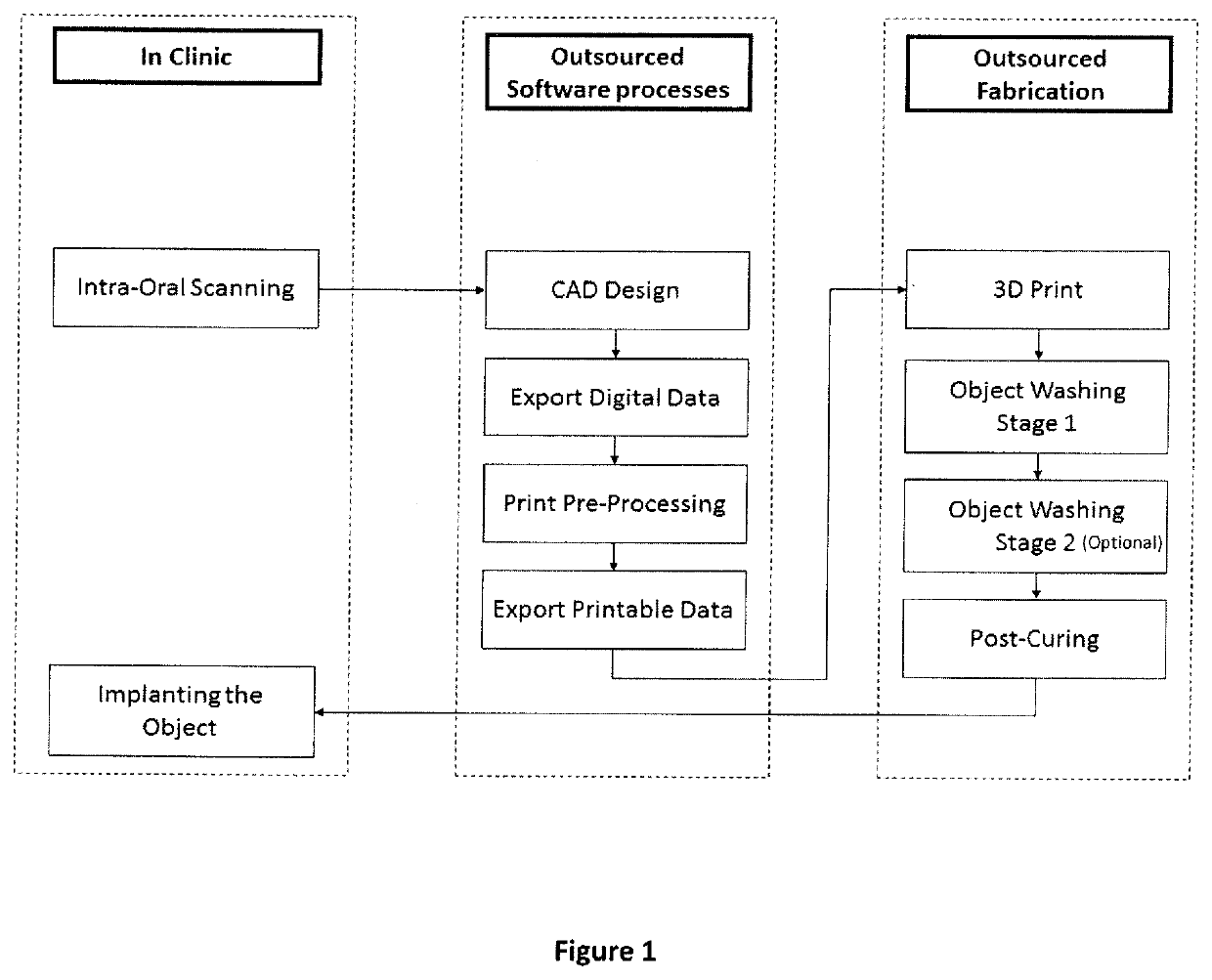
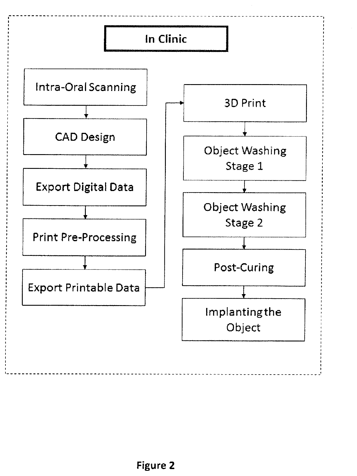
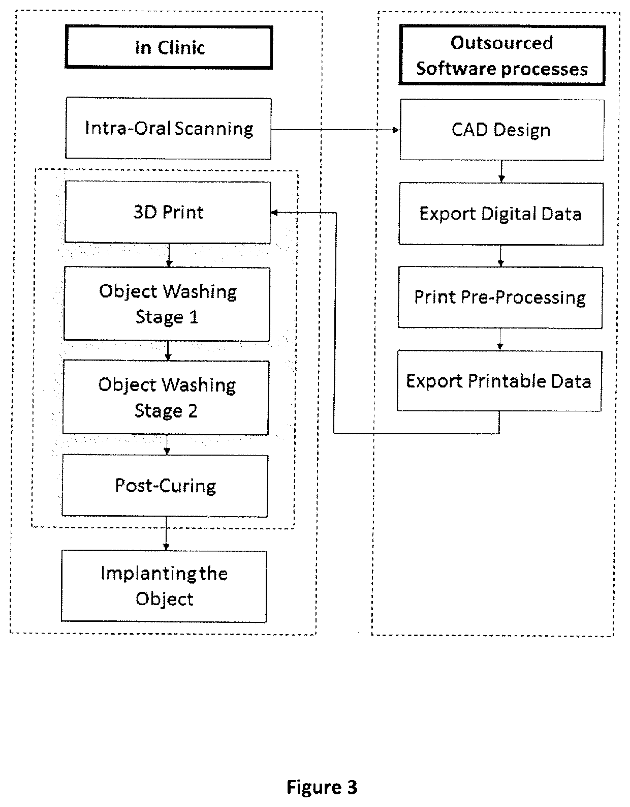
[0029]Referring to FIG. 3, the invention comprises firstly capturing the patient's anatomy in the same way a clinician would normally do in the dental clinic, either by means of an intra-oral scanning or by creating a physical impression which may also be 3D scanned. Subsequently, the 3D data is sent out to an external facility, data / information support service, web portal, an area network (local or otherwise) or a cloud-based service, thus enabling actual work to be carried out from anywhere in the world. The work may also be partially, completely automated or completely non-automated (i.e. operated by humans at the back-end which may be centralized in one or more locations, or distributed decentralized as well), so that the outsourced software processes such as, but not limited to, file fixing, support generation (automatic or manual), parts arrangement, slicing to printable file, CAD design, exportation of digital data, pre-processing printing or exportation of printable data may...


PUM

PropertyMeasurementUnit
degrees of freedomaaaaaaaaaa
transparentaaaaaaaaaa

Abstract

A device comprising; a controller arranged to receive data for an article to print; a sub-device comprising a resin source arranged to provide material for printing the article; a radiation source arranged to direct radiation for the printing of said article; a plurality of stations, said stations including a printing tank in which the article is printed, at least one cleaning station for cleaning the printed article and a curing station arranged to at least partially complete the curing of the printed article; a build surface upon which the article is arranged to be printed; wherein controller is arranged to move the build surface and the plurality of stations relative to each other.

Description

TECHNICAL FIELD[0001]This invention relates to a method for decentralization of automated additive manufacturing, while centralizing the pre-processing work, as well as a device capable of additive manufacturing with integrated and automated post-processing for facilitating the method.BACKGROUND[0002]It is common practice in the current state of the art, where additive manufacturing processes, including stereolithography (SLA) process (but not limited to), typically comprise of three phases (i.e. Design and Pre-processing, 3D printing and Post-processing), with each phrase requiring an immense amount of human involvement, effort and contribution.[0003]The first phase Design and Pre-Processing involves both Computer Aided Design (CAD) and Computer Aided Manufacturing (CAM) steps, which are integral to digital file preparation. The first CAD step designs and optimizes digital 3D files for the additive manufacturing process. The second CAM step prepares the 3D model for printing on the...

Claims


Application Information

Patent Timeline
Patent Type & Authority Applications(United States)
IPC IPC(8): B29C64/129B29C64/255B29C64/264B29C64/35B29C64/245B29C64/393B29C64/379B29C64/241B29C64/232B29C64/236
CPCB29C64/35B29C64/264B29C64/245B29C64/129B29C64/393B29C64/255B29C64/379B29C64/241B33Y30/00B29C64/232B33Y10/00B29C64/236B33Y40/20B33Y50/02B29C64/20B29C2071/0027B29C71/04A61C9/0053A61C13/0019A61C13/0004A61C9/0006A61C8/00B08B3/10A61C13/0006B29C64/124B29C64/386B29L2031/7536B29C71/0009B29C2071/0045B29C2035/0827B29C64/227B33Y40/00
Inventor VAN ESBROECK, HUBERTUS THEODORUS PETRUSSUWONO, BOYLEGUPTA, HARSH
Owner STRUCTO
Why Eureka
Try Eureka