Method for acquiring and modelling an incident wind field by means of a lidar sensor

a lidar sensor and incident wind field technology, applied in the field of lidar (light detection and ranging) sensors, can solve the problems of unrealistic, exploitable for real-time applications, and assumption that is neither representative nor realistic, and achieve reliable and accurate measurements.

Active Publication Date: 2020-04-23
INST FR DU PETROLE
View PDF0 Cites 23 Cited by
  • Summary
  • Abstract
  • Description
  • Claims
  • Application Information

AI Technical Summary

Benefits of technology

[0024]Using such a cost function makes it possible to estimate the wind speed at an estimation point. Besides, such a function allows to have a clear interpretation of weighting matrices P0, Q, Rs and Rm.
[0025]According to an aspect of the invention, the wind amplitude and direction measurements at the different measurement points are carried out at a sampling rate of at least 0.25 Hz. Using such a sampling frequency range allows to obtain several simultaneous measurements on the same measurement axis while having reliable and accurate measurements.

Problems solved by technology

However, this assumption is neither representative nor realistic since the wind speed varies considerably with altitude within the atmospheric boundary layer, with very complicated dynamics.
Furthermore, the technique as described in this publication rests on an unrealistic assumption according to which all the measurements performed with a LiDAR sensor are available for all the beams, at the same time.
The longitudinal wind speed and the direction are obtained only on the basis of a moving average, and they are not exploitable for real-time applications.
Indeed, the main sources of the damage inflicted on the structure and the elements of the wind turbine are related to the wind conditions involving extreme loads (strong turbulent wind, gusts) and to the fatigue of the materials subjected to vibrational and oscillating phenomena.
The latter are generated by the interactions between the wind turbine and the wind field, with notably vibration problems exciting the eigenmodes of the wind turbine.
There are some control strategies that are currently implemented, but they have no reliable wind information integrable in the control loop to ensure the planned service life.
There may also be an alignment from an anemometer sensor arranged in a turbulent zone (nacelle) and undergoing drifts, which leads to an often misaligned wind turbine.
In all cases, this requires integrating constraints in the wind turbine design, with reinforced structures and an associated additional investment cost, as well as a production loss and associated structure load risks.

Method used


Image

  • Method for acquiring and modelling an incident wind field by means of a lidar sensor
  • Method for acquiring and modelling an incident wind field by means of a lidar sensor
  • Method for acquiring and modelling an incident wind field by means of a lidar sensor

Examples


Embodiment Construction

[0058]Notations

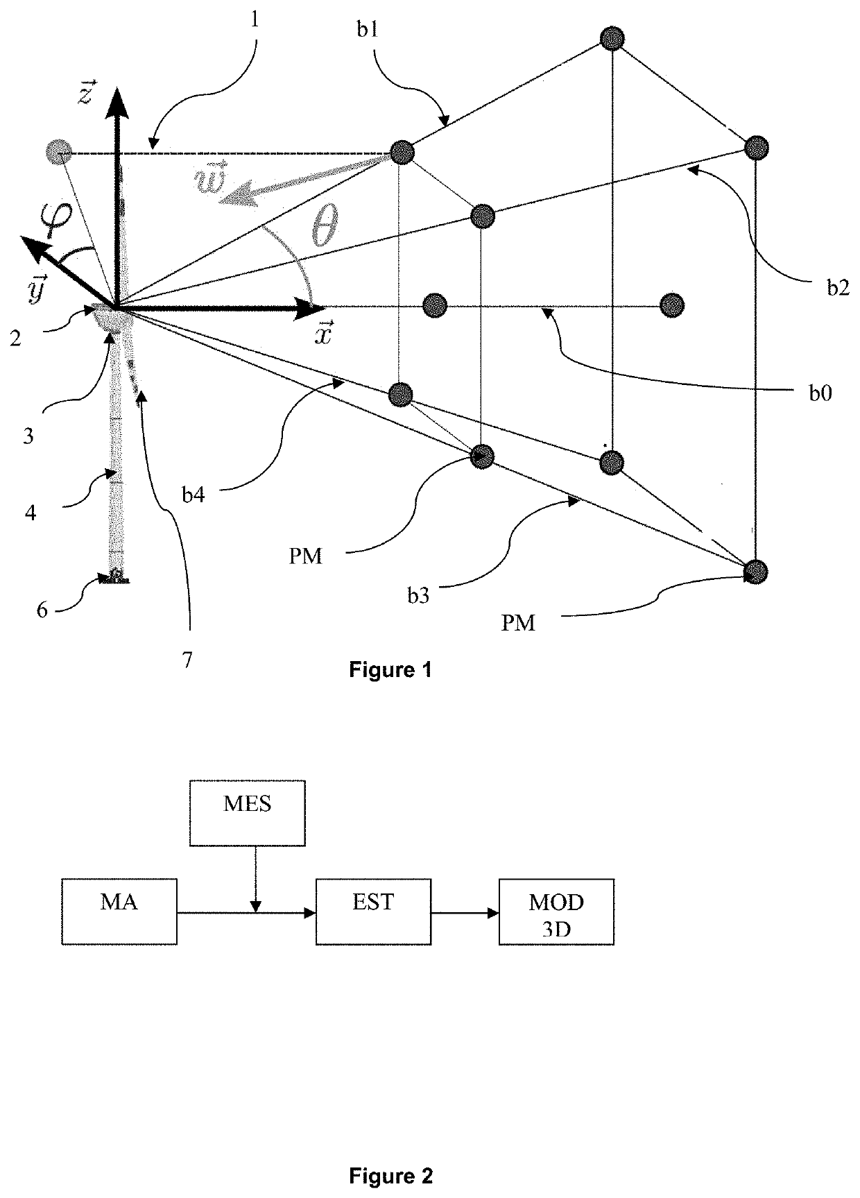
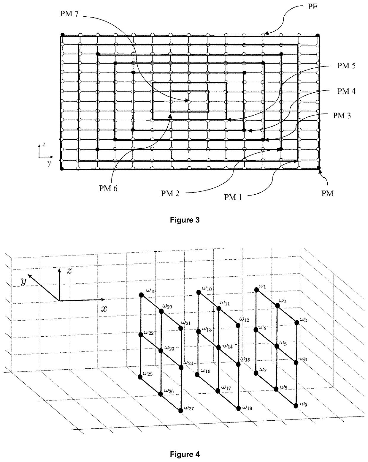
[0059]The following notations are used in the description hereafter:[0060]x, y, z: directions of the three-dimensional coordinate system, with z the vertical axis and x the principal direction of the wind,[0061]θ and φ: orientation angles of said LiDAR sensor. These angles are described in FIG. 1: angle θ is the angle formed by the projection of the measurement angle of the LiDAR onto the plane (y, z) and φ is the angle formed by the projection of the measurement axis of the LiDAR onto a plane consisting of axis x and the projection of the measurement axis of the LiDAR onto plane (y, z),[0062]m(t): measurement of the LiDAR sensor at a measurement point,[0063]vj,x(k), vj,z(k), vj,z(k): projections of the wind speed onto x, y, z,[0064]ω: ordered vector comprised of all the components of the wind speed at the points in space where the wind is estimated on axes x, y and z of the three-dimensional coordinate system,[0065]{circumflex over (ω)}(t): estimation of ω(t) at the ...


PUM


Abstract

The object of the invention relates to a method for acquisition and modelling of an incident wind field by a LiDAR sensor. Acquisition and modelling include a step of estimating the wind amplitudes and directions for a set of discretized points, and a step of incident wind field reconstruction in three dimensions and in real time. The invention also relates to a method of controlling and/or monitoring a wind turbine equipped with such a LiDAR sensor from the incident wind field reconstructed in three dimensions and in real time.

Description

FIELD OF THE INVENTION[0001]The present invention relates to the field of LiDAR (Light Detection And Ranging) sensors used as a remote sensing means for measuring wind speed. It also relates to the field of wind turbines equipped with LiDAR sensors and to the control thereof.[0002]The performances of LiDAR sensors in terms of measurement accuracy, reliability and availability allow to work out wind state estimations and predictions for a targeted aerosol volume. However, LiDAR sensors have some limitations in terms of data accuracy and availability. On the one hand, they only provide a raw wind measurement, i.e. a projection of the wind on a measurement axis (also referred to as LASER—Light Amplification by Stimulated Emission of Radiation—beam) and, on the other hand, they only allow access to a limited bandwidth corrupted with the spectral content of the wind. Since the raw measurement is an indirect wind measurement corresponding to the projection of the wind on the axis of a LAS...

Claims


Application Information

Patent Timeline
Patent Type & Authority Applications(United States)
IPC IPC(8): F03D7/04G01S17/95
CPCF05B2200/261F05B2270/404F05B2260/84F03D7/045F05B2200/11F05B2200/262G01S17/95G01S17/58Y02A90/10Y02E10/72F05B2270/8042
Inventor NGUYEN, HOAI-NAMGUILLEMIN, FABRICE
Owner INST FR DU PETROLE
Why Eureka
Try Eureka