Mechanoluminescent Devices, Articles, and Methods
a technology of electromagnetic radiation and light source, applied in the direction of force measurement by measuring optical property variation, analysis by material excitation, structural/machine measurement, etc., can solve the problems of limiting their use in these types of applications and others, limiting their use in practical applications, and limiting electric power
- Summary
- Abstract
- Description
- Claims
- Application Information
AI Technical Summary
Benefits of technology
Problems solved by technology
Method used
Image
Examples
example 1
ving Lateral Architecture
[0100]A device having a lateral architecture was fabricated in this example. The device of this example was a fully integrated mechanoluminescent-perovskite flexible and bendable pressure sensor having a lateral structure according to the schematic of FIG. 2C. The layers of the device of this example included polyimide (210 of FIG. 2C) / ZnS:Cu-PDMS (230 of FIG. 2C) / perovskite (220 of FIG. 2C) / Au (210 of FIG. 2C).
[0101]A polyimide substrate was treated with plasma cleaning, and onto the substrate the ZnS:Cu / PDMS composite was deposited using spin coating.
[0102]PDMS was cured on a hot plate at 150° C. for 5 minutes. The top surface of the ZnS:Cu / PDMS was treated with plasma cleaning to make the surface hydrophilic. A 2D Ruddlesden-Proper perovskite (n=3) was then spin-coated on the ZnS:Cu / PDMS layer with 2000 rpm for 45 seconds, and baked on a hot plate for 5 minutes. A 80 nm gold coating was deposited on the perovskite layer.
[0103]Spin-coating the perovskite o...
example 2
ving Lateral Architecture
[0107]In this example, a pressure sensor was fabricated that included two functional layers: i) a ZnS:Cu / PDMS composite as a light source, and ii) a perovskite as a photoactive layer.
[0108]The pressure sensors of this example had a structure according to FIG. 2E and FIG. 2F, and were fabricated, as explained in detail below, by sequentially depositing perovskite layer (220 of FIG. 2E), PMMA (240 of FIG. 2E, FIG. 2F), and ZnS:Cu-PDMS (230 of FIG. 2E) composite layer on flexible PET substrates (250 of FIG. 250). The ultra-thin, highly transparent PMMA layer allowed the transmission of ML light without, or with very little, loss.
[0109]ML light was emitted by ZnS:Cu particles in response to an applied pressure or strain, and was transmitted through a translucent PMMA later to the perovskite layer.
[0110]FIG. 4 is a schematic of the likely mechanism of the photo-sensing material as a hole-only device, wherein the electrons are trapped and holes are mobile.
[0111]PE...
example 3
Type Device
[0144]In this example, a flexible pressure sensor was fabricated, which included a 2D Ruddlesden-Popper perovskite. This perovskite had a relatively robust material stability. The device architecture was a vertical type structure, which likely contributed, at least in part, to its comparatively easy fabrication and efficient ML harvesting.
[0145]Unlike other conventional pressure sensors, the ML-perovskite flexible pressure sensor of this example did not require any power at the sensing location.
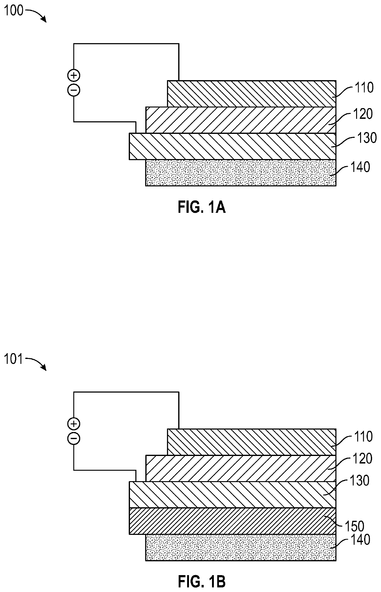
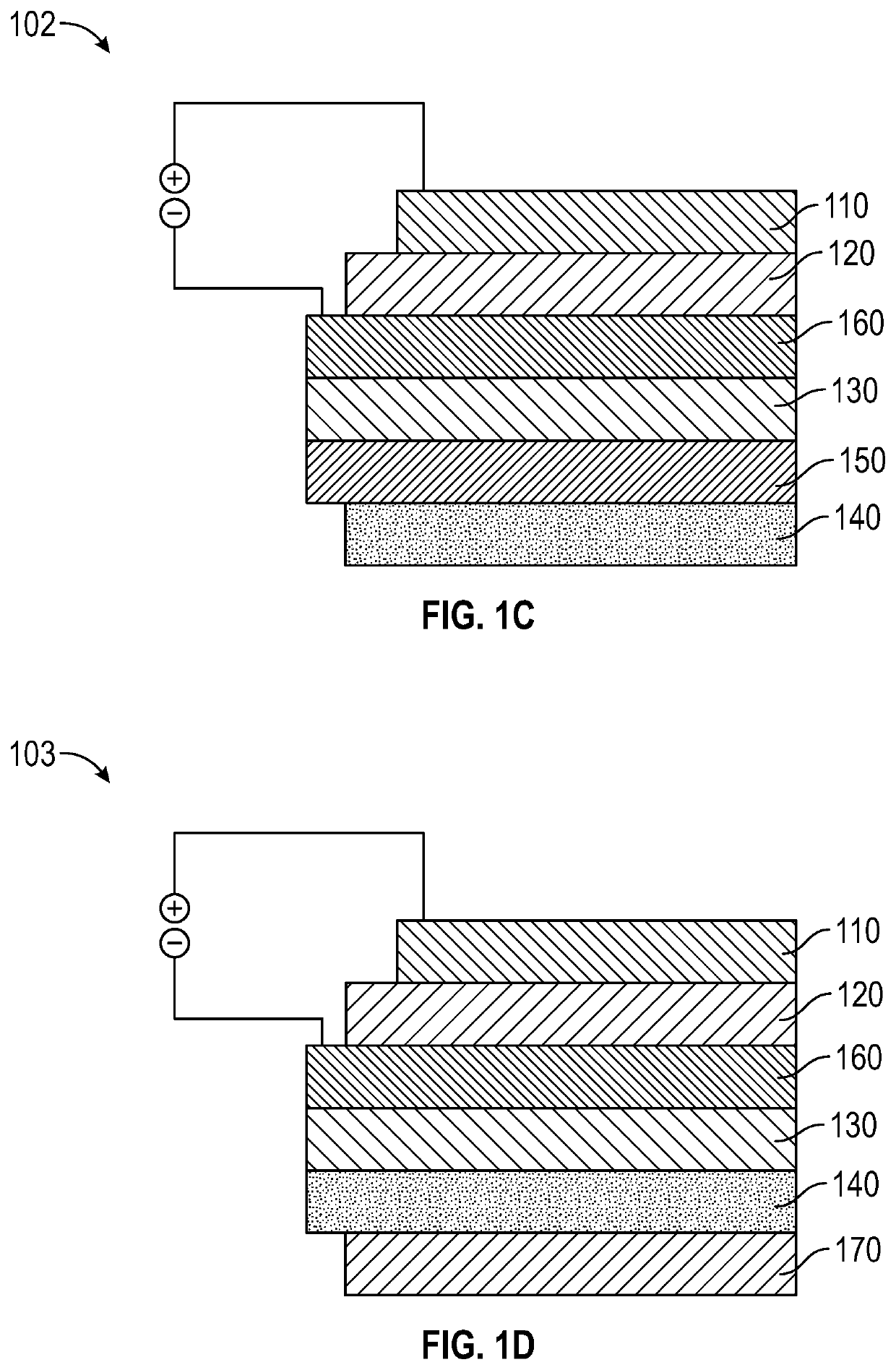
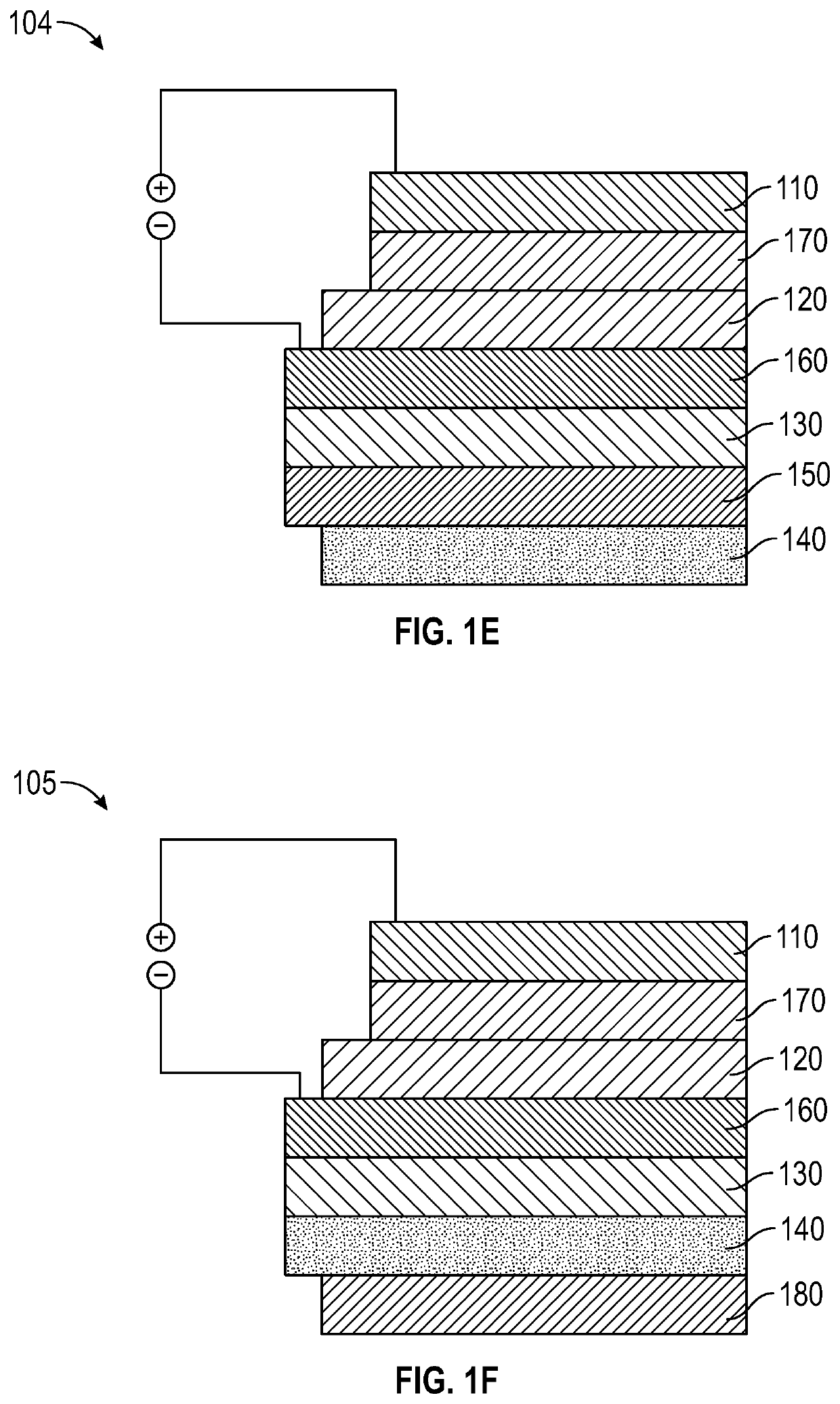
[0146]The device of this example had a vertical architecture, similar to the architecture depicted at FIG. 1C, and included the following layers: (ZnS:Cu-PDMS / PET / In2O3—Au—Ag / bl-TiO2 / perovskite / Au).
[0147]The device included a thin flexible ZnS:Cu / PDMS film on a transparent poly(ethylene terephthalate) (PET) substrate and a 2D Ruddlesden-Popper layered perovskite ((BA)2(MA)2Pb3I10). A band energy diagram of the device is depicted at FIG. 7.
[0148]ZnS:Cu crystals emitted ML light at 5...
PUM
| Property | Measurement | Unit |
|---|---|---|
| bias voltage | aaaaa | aaaaa |
| bias voltage | aaaaa | aaaaa |
| transmittance | aaaaa | aaaaa |
Abstract
Description
Claims
Application Information
 - R&D
- Intellectual Property
- Life Sciences
- Materials
- Tech Scout
- Unparalleled Data Quality
- Higher Quality Content
- 60% Fewer Hallucinations
Browse by: Latest US Patents, China's latest patents, Technical Efficacy Thesaurus, Application Domain, Technology Topic, Popular Technical Reports.
© 2025 PatSnap. All rights reserved.Legal|Privacy policy|Modern Slavery Act Transparency Statement|Sitemap|About US| Contact US: help@patsnap.com


