
High efficiency powder dispersion and blend system and method for use in well completion operations

a powder dispersion and blend system technology, applied in the direction of mixing, transportation and packaging, well accessories, etc., can solve the problems of affecting the hydrating effect of water sensitive powders, the exposure of workers and environmental cleanup hazards, and the inability to meet the requirements of a high-efficiency powder dispersion system, so as to avoid the inability to hydrate water-sensitive powders. , the effect of avoiding the inability to meet the requirements of a high-efficiency powder disper

Active Publication Date: 2020-04-30
TRAHAN DAVID O +1
View PDF22 Cites 9 Cited by
  • Summary
  • Abstract
  • Description
  • Claims
  • Application Information

AI Technical Summary

Benefits of technology

The invention is about delivering chemical powders to a well site using special containers or bulk trailers. The powders are preloaded with a low-dew point air to prevent water absorption. The air is then used to transfer and meter the powders using pumps or a constant flow of air. The invention also includes a sensor to measure the dew point of the air and an electronic control system to stop the air flow if it becomes too moist. This prevents the powders from hydrating and forming lumps that could damage the equipment.

Problems solved by technology

Additionally, liquid chemical products delivered to well site in bulk shipping containers are more susceptible to leakage or spillage than products delivered as powders.
Liquid chemical spills create possible exposure issues to workers and environmental cleanup hazards.
There are several limitations associated with the use of this type of traditional eductor blending system.
Manually pouring the powders into the eductor overhead receptacle can lead to premature liquid wetting causing plugging of the eductor suction section, resulting in inconsistent feed rate.
Further, the traditional powder eductor apparatus and blending methods require considerable operator effort to accurately meter powdered chemical products into a flowing liquid system.
The traditional eductor powder addition method makes it more difficult for operators to accurately meter powders into a continuous flow of liquid.
The addition of hydratable polymeric powders into water systems at high volumetric flow rates presents special problems for well service operators.
If the powder is added too quickly it will only partially hydrate in the water or liquid, resulting in reduced product performance.
Blending difficult-to-hydrate polymers at high addition rates into water and liquid systems places special challenges on powder addition and blending systems.
When hydratable polymer powders are highly hygroscopic and improperly dispersed, they tend to form small partially hydrated polymer particles encapsulated in highly viscous, partially hydrated gel.
The existence of partially hydrated fish eyes in well service water or liquids is unacceptable for well site operations.
However, there are drawbacks to using high energy mixing systems.
In the case of high molecular weight polymers which are used in water or liquid systems, the polymer can be mechanically sheared, damaging the physical characteristics and performance properties of the powder after it is solubilized into the water or liquid.
Another limitation of current conventional mobile powder dispersion system involves the powder handling and feed system.
Many of the chemical powders used in well operations are hygroscopic, water-seeking, and easily absorb atmospheric moisture, becoming “sticky” and difficult to flow.
When working with friction reducing polyacrylamide-based polymers, the atmospheric moisture can cause the polymer to build up on the internal surface of handling equipment and hoses it comes in contact with, resulting in the interruption in normal operations.

Method used


Image

  • High efficiency powder dispersion and blend system and method for use in well completion operations
  • High efficiency powder dispersion and blend system and method for use in well completion operations
  • High efficiency powder dispersion and blend system and method for use in well completion operations

Examples


Embodiment Construction

[0025]Before describing selected embodiments of the present disclosure in detail, it is to be understood that the present invention is not limited to the embodiments described herein. The disclosure and description herein is illustrative and explanatory of one or more presently preferred embodiments and variations thereof, and it will be appreciated by those skilled in the art that various changes in the design, organization, order of operation, means of operation, equipment structures and location, methodology, and use of mechanical equivalents may be made without departing from the spirit of the invention.

[0026]As well, it should be understood the drawings are intended to illustrate and plainly disclose presently preferred embodiments to one of skill in the art, but are not intended to be manufacturing level drawings or renditions of final products and may include simplified conceptual views as desired for easier and quicker understanding or explanation. As well, the relative size...


PUM

PropertyMeasurementUnit
dew pointaaaaaaaaaa
particle sizeaaaaaaaaaa
angleaaaaaaaaaa

Abstract

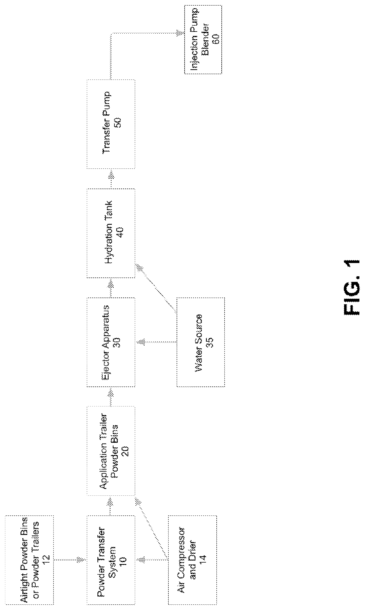
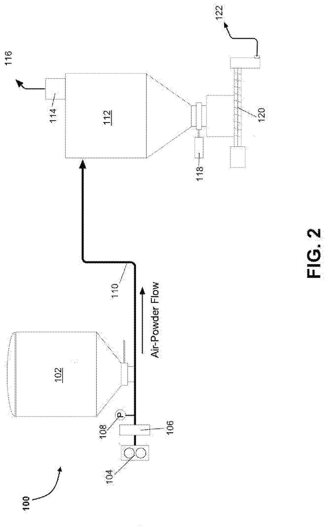
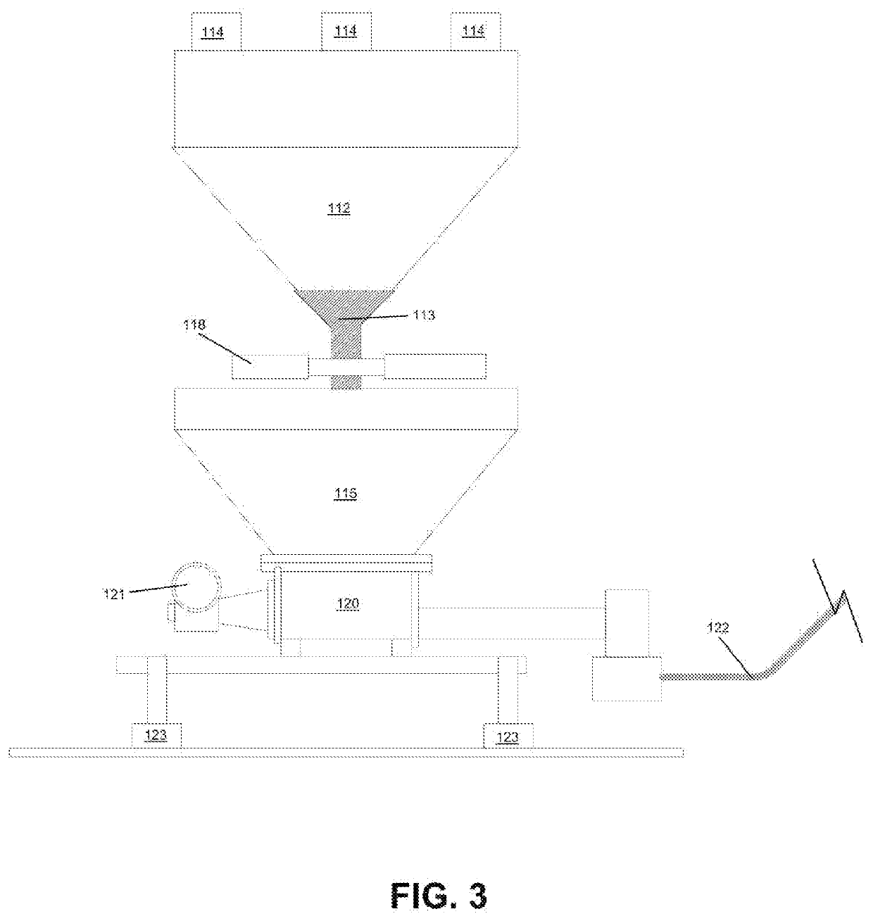
An improved system and method for fluidizing dry powder-based additives into downhole well operations utilizes a dried, low-volume air stream and an ejector nozzle in order to disperse the powders into a liquid stream. In an embodiment, the system can be placed on a powder blending trailer in order to convey additives directly from bulk transport bins into a liquid stream, through the use of an atmospheric pressure hydration tank fitted with a cyclone separator to ensure an even dispersal into the liquid stream.

Description

REFERENCE[0001]This is a non-provisional patent application claiming priority to U.S. Provisional Application No. 62 / 751,359, filed 26 Oct. 2018, with the same title and inventors. The contents of this provisional application are fully incorporated herein by reference.FIELD[0002]The present invention relates to a mobile polymer blend method and apparatus for blending one or more water-soluble powdered polymer(s) and chemicals into fresh or non-fresh water at well drilling, completion or fracture locations. The polymer powder can include a wide assortment of polymer additives less than 400 micrometers in particle size which are typically used in such operations. The powdered chemicals may comprise scale inhibitors, corrosion inhibitors, biocides, surfactants, iron control agents, polymer breakers, and other powdered chemical products used in liquid applications.[0003]The process and apparatus comprises a mobile powder blending trailer and an air compressor with an air dryer, connecte...

Claims


Application Information

Patent Timeline
Patent Type & Authority Applications(United States)
IPC IPC(8): B01F3/12B01F15/00B01F5/04B01F15/02B01F3/20E21B41/00B01F23/70
CPCB01F15/00974B01F2003/125B01F3/1271B01F15/00194B01F5/043B01F2215/0081B01F15/00961B01F15/0202B01F15/0259B01F15/026B01F15/0251B01F15/0283B01F5/0426B01F15/0235E21B41/00B01F3/2028B01F23/50B01F25/31241B01F35/2117B01F35/711B01F23/59B01F23/704B01F25/31243B01F35/184B01F35/187B01F35/7544B01F35/71731B01F35/71775B01F35/71801B01F35/71805B01F23/56B01F2101/49
Inventor TRAHAN, DAVID O.TRAHAN, RICHARD E.
Owner TRAHAN DAVID O
Learn More