Method of separating pellicle and device for separating pellicle

Active Publication Date: 2020-04-30
SHIN ETSU CHEM IND CO LTD
View PDF10 Cites 1 Cited by
  • Summary
  • Abstract
  • Description
  • Claims
  • Application Information

AI Technical Summary

Benefits of technology

The invention provides a way to separate a pellicle from an exposure plate without leaving behind any residue that could affect the quality of the exposure. Additionally, the method allows the exposure plate to be washed again using mild cleaning conditions.

Problems solved by technology

As described previously, the phase-shifting film is significantly delicate, and thus the phase-shifting film may be damaged by excessive mask washing.
In the conventional method of separating the pellicle with the separation jig described above, a force beyond an adhesive force is applied between the exposure original plate and the adhesive layer so as to forcefully peel off, from the surface of the exposure original plate, the pellicle including the adhesive layer, and thus a large amount of residue of the adhesive layer is left on the exposure original plate, with the result that it is troublesome to perform the subsequent washing.
When the pellicle is separated from the top of the exposure original plate, it is likely that the adhesive layer is displaced so as to stick to the pattern of the exposure original plate, and that thus the pattern is damaged or contaminated.
Furthermore, in a large-sized pellicle in which the lengths of sides of the pellicle are long, since the entire pellicle cannot be separated in a stroke, the pellicle needs to be separated part by part, and thus it is necessary to perform such separation that the previously separated part is prevented from being adhered again, with the result that workability is poor.

Method used


Image

  • Method of separating pellicle and device for separating pellicle
  • Method of separating pellicle and device for separating pellicle
  • Method of separating pellicle and device for separating pellicle

Examples


example 1

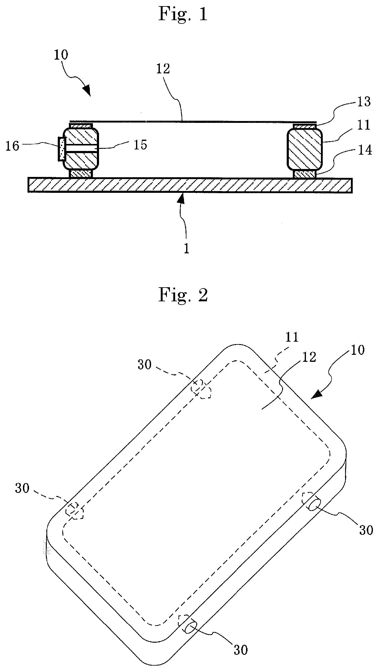
[0070]The production of a pellicle which was used in example 1 will first be described. A pellicle frame made of an aluminum alloy (outer size 149 mm×115 mm×3.5 mm×wall thickness 2 mm, the flatness of an end surface to be coated with a sticky agent for sticking a mask, 15 um) was accurately washed, then the end surface to be coated with the sticky agent was coated with an acrylic sticky agent (product name: SK-Dyne, SK-1425) made by Soken Chemical & Engineering Co., Ltd. and was left at room temperature for 60 minutes so as to provide the sticky agent, thereafter a separator was placed on an upper surface portion (whose flatness was 5 um) of an aluminum plate which was larger than the pellicle frame and the pellicle frame coated with the sticky agent described above was placed with the sticky agent facing downward. In this way, the sticky agent was brought into contact with the flat separator so as to be subjected to flattening processing. Then, the pellicle frame on the aluminum pl...

example 2

[0073]A pellicle completed by the same procedure as in example 1 was stuck to the same 6025 mask substrate as in example 1 and was left at room temperature for 7 days. After 7 days, the mask substrate to which the pellicle described above was stuck was set on the separation device described above. Here, a separation test was performed while the control of the separation device was being performed by collectively controlling two pellicle frame support pins 21 inserted into the jig holes of the same side on each of the sides. When the operation of the separation device during the separation test was observed, as compared with the case where the four pellicle frame support pins 21 were independently controlled in example 1, a separation strength was slightly increased. However, although the substrate after the separation was visually checked, a remarkable separation residue was not confirmed. The maximum separation strength when the pellicle was separated was 10.2 N.

example 3

[0074]A pellicle completed by the same procedure as in example 1 was stuck to the same 6025 mask substrate as in example 1 and was left at room temperature for 7 days. After 7 days, the mask substrate to which the pellicle described above was stuck was set on the separation device described above. Here, separation was performed while the control of the separation device was being performed by collectively controlling pellicle frame support pins inserted into jig holes. As compared with the case where the four pellicle frame support pins 21 were independently controlled and the separation was performed in example 1 and the case where the control was performed on each of the sides opposite each other and the separation was performed in example 2, a separation strength was slightly increased. However, although the substrate after the separation was visually checked, a remarkable separation residue was not confirmed. The maximum separation strength when the pellicle was separated was 12...


PUM


Abstract

To provide a method of separating a pellicle and a device for separating a pellicle which can reduce the amount of residue left on an exposure original plate when the pellicle is separated from the exposure original plate and which can wash again the exposure original plate under mitigated washing conditions, a pellicle frame support pin is inserted into a jig hole provided in an outer surface of the pellicle frame, the pellicle frame support pin is moved in a direction in which the pellicle is separated from the exposure original plate, a separation force applied by the movement to the pellicle frame support pin is measured and the pellicle is separated from the exposure original plate while control is being performed such that the separation force is minimized.

Description

FIELD OF THE INVENTION[0001]The present invention relates to a method of separating a pellicle which is used as a dust fender for a lithography mask when a semiconductor device such as LSI, VLSI or the like or a liquid crystal display board is manufactured and to a device for separating the pellicle.BACKGROUND TECHNOLOGY[0002]In manufacturing semiconductor such as LSI, VLSI or the like, or in manufacturing a liquid crystal display board or the like, an exposure original plate is overlaid on a resist coated surface of a semiconductor wafer or a liquid crystal substrate, and a latent image pattern is formed on the resist by irradiating collimated light. At this time, when dust is adhered to the exposure original plate, the dust absorbs or bents the light causing deformation of a transferred pattern, roughen edges and black stains on a base, with the result that dimensions, quality, appearance and the like are disadvantageously degraded. It is noted that in the present invention, the “...

Claims


Application Information

Patent Timeline
IPC IPC(8): G03F1/62G03F7/20
CPCG03F1/62G03F7/7015G03F1/64G03F1/82G03F7/70908G03F7/70983G03F7/343G03F7/42B32B38/10B32B43/006
Inventor HAMADA, YUICHI
Owner SHIN ETSU CHEM IND CO LTD
Why Eureka
Try Eureka