
Wide-range high mass resolution in reflector time-of-flight mass spectrometers

a mass spectrometer and reflector technology, applied in the field of energyfocusing and solidanglefocusing reflectors for time-of-flight mass spectrometers, can solve the problems of unwieldy, unreflectable mamyrin reflectors, and difficult to achieve the effect of facilitating economic viable use, sufficient sensitivity and good results

Active Publication Date: 2020-05-14
BRUKER DALTONIK GMBH & CO KG
View PDF0 Cites 0 Cited by
  • Summary
  • Abstract
  • Description
  • Claims
  • Application Information

AI Technical Summary

Benefits of technology

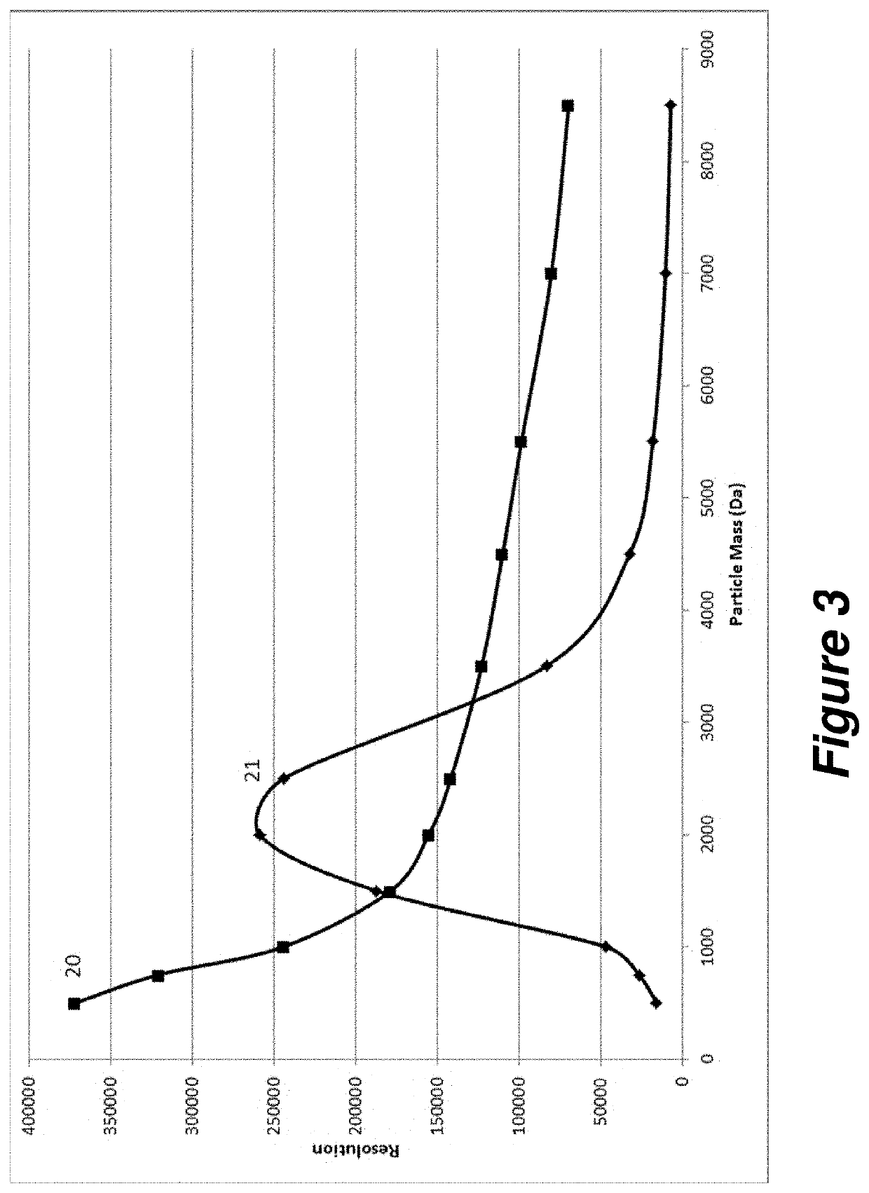
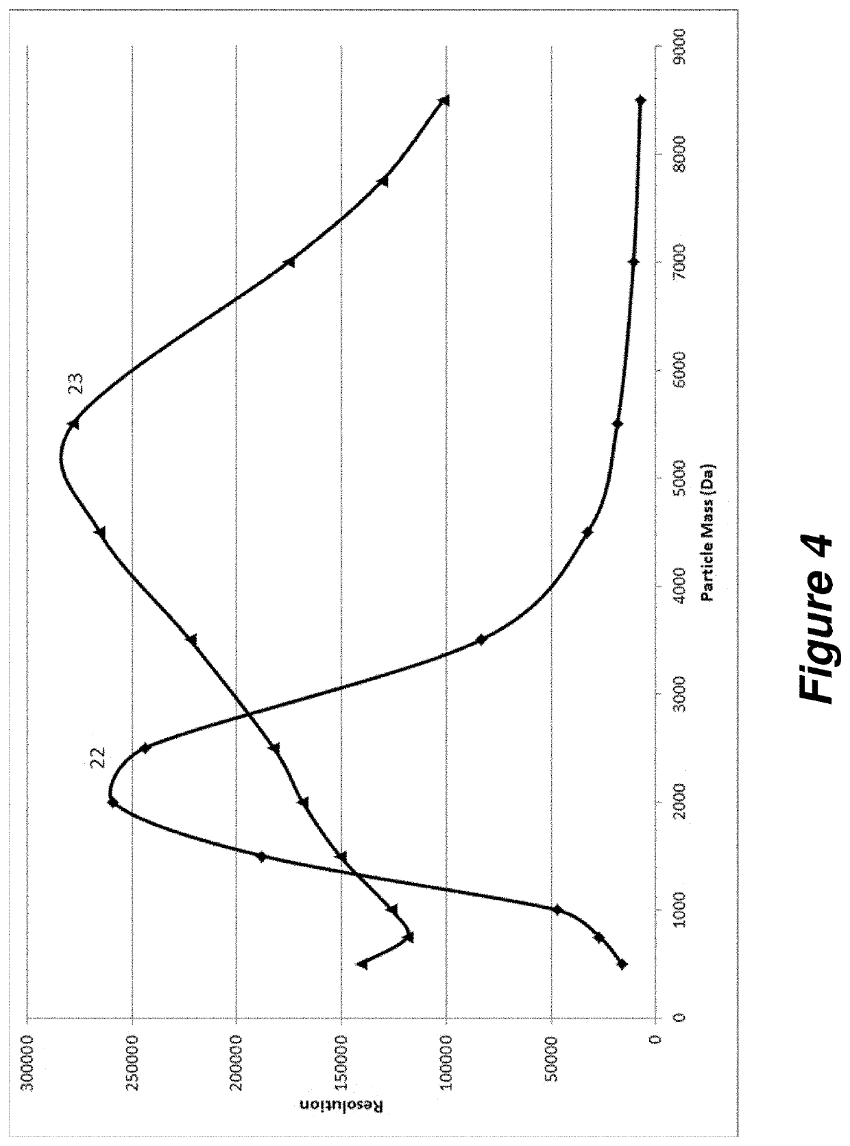
[0013]The best possible time functions for the changes in the voltages, e.g. U3=f(t), can be determined in simulations. Simulations have shown that even above a mass m=8 kilodaltons, it is possible to achieve mass resolutions of R=m / Δm>100,000 (Δm represents the full width at half-maximum of the ion signal). Resolution and sensitivity in this high mass range can thus be up to ten times higher than with the static reflector mode known to date. This facilitates the economically viable use of reflector time-of-flight mass spectrometers as protein sequencers, which requires the mass spectrum to be measured over a wide range of up to roughly 12 kilodaltons (around 100 amino acids) with sufficient sensitivity and sufficient mass resolving power, preferably spanning substantially more than 1000 Dalton, such as 2000 Dalton, 4000 Dalton, 6000 Dalton or more. It is thus possible to sequence proteins or protein digest fragments up to a length of around 200 amino acids in one step.

Problems solved by technology

This Mamyrin reflector cannot, however, reflect fragment ions so that they are energy-focused because it reflects and simultaneously focuses only ions of the original energy, which all have the same penetration depth.
This method is very time consuming and therefore unwieldy because of the necessity to acquire a large number of individual spectra with slightly different voltage settings.

Method used


Image

  • Wide-range high mass resolution in reflector time-of-flight mass spectrometers
  • Wide-range high mass resolution in reflector time-of-flight mass spectrometers
  • Wide-range high mass resolution in reflector time-of-flight mass spectrometers

Examples


Embodiment Construction

[0021]While the invention has been illustrated and explained with reference to a number of embodiments, those skilled in the art will recognize that various changes in form and detail may be made herein without departing from the scope of the technical teaching as defined in the enclosed claims.

[0022]The objective of the invention is to generate high mass resolution over wide mass ranges up to high masses of, for example, around twelve kilodaltons (one dalton corresponds to one atomic mass unit u) by varying at least one voltage on one of the diaphragms of the reflector according to a suitable time function while the spectrum is being acquired so that the different ions which pass successively through the reflector are subjected to the most favorable reflector settings so as to be optimally focused.

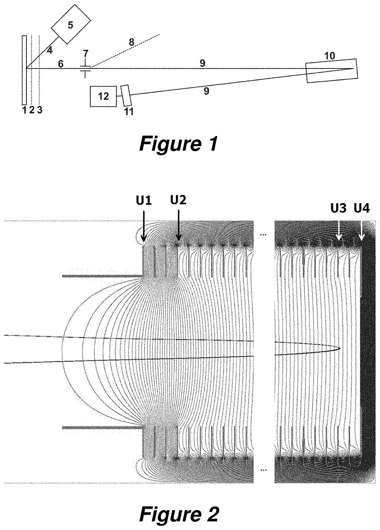
[0023]How a MALDI time-of-flight mass spectrometer operates can be seen from the rough schematic in FIG. 1. A relatively large number of samples or a tissue section to be imaged are / is lo...


PUM


Abstract

The invention relates to the operation of an energy-focusing and solid-angle-focusing reflector for time-of-flight mass spectrometers with pulsed ion acceleration into a flight tube, e.g. from an ion source with ionization by matrix-assisted laser desorption (MALDI). The objective of the invention is to generate high mass resolution in wide mass ranges up to high masses above eight kilodaltons by varying at least one operating voltage on one of the diaphragms of the reflector which can be varied according to a suitable time function during the spectrum acquisition. It may also be advantageous to adapt the operation of the accelerating voltages in the starting region of the ions accordingly. These measures make it possible to achieve a mass resolution much higher than R=100,000 in a wide mass range extending up to and above eight kilodaltons.

Description

BACKGROUND OF THE INVENTIONField of the Invention[0001]The invention relates to the operation of an energy-focusing and solid-angle-focusing reflector for time-of-flight mass spectrometers with pulsed ion acceleration into a time-of-flight tube, e.g. from an ion source with ionization by matrix-assisted laser desorption (MALDI).Description of the Related Art[0002]Two-stage reflectors with two grids between two field stages are known from the work of B. A. Mamyrin, V. I. Karatzev and D. V. Shmikk (U.S. Pat. No. 4,072,862 A). They allow a velocity-focusing ion reflection with adjustable focal length (usually called “energy focusing” nowadays). A first, strong opposing field decelerates the ions, while a second, very homogeneous field reflects the ions and in doing so brings about velocity focusing because ions of a higher velocity penetrate more deeply into the reflector and thus have to cover a greater distance, thereby experiencing a delay, which compensates for their higher velocit...

Claims


Application Information

Patent Timeline
Patent Type & Authority Applications(United States)
IPC IPC(8): H01J49/16H01J49/40H01J49/04
CPCH01J49/403H01J49/164H01J49/405H01J49/0418H01J49/0031
Inventor BÖHM, SEBASTIANHAASE, ANDREAS
Owner BRUKER DALTONIK GMBH & CO KG
Learn More