System and Method for Light Emitting Diode (LED) Display Repair

a technology of light-emitting diodes and display panels, applied in the field of display technology, can solve the problems of affecting the operation of display panels, and reducing the efficiency of light-emitting diodes, so as to increase the operating voltage of pixels, reduce power consumption, and increase assembly yield

Active Publication Date: 2020-05-14
ELUX INC
View PDF0 Cites 15 Cited by
  • Summary
  • Abstract
  • Description
  • Claims
  • Application Information

AI Technical Summary

Benefits of technology

[0012]Disclosed herein are light emitting diode (LED) pixel drive circuits that can be used to repair some common defects that result in non-working pixels. One circuit uses redundant LEDs in parallel to compensate for missing or non-connected LEDs, effectively increasing assembly yield. A second circuit connects LEDs in series to increase the pixel operating voltage, so less power is dissipated in the TFT circuit, which increases the display efficiency. For the series connection, a missing or unconnected LED causes the circuit to fail, so a repair structure is used to shunt current around a defect site. For LEDs connected in parallel, a shorted LED drops the supply voltage to ground, preventing illumination of the other functional LEDs. So the repair structure is a laser fuse to disconnect the defect site.

Problems solved by technology

The switching transistor only consumes power during writing.
The power is used to produce light from the LED, but the drive transistor also dissipates a significant portion of total power.
The TFT transistors are fabricated at temperatures below the melting temperature of the substrate and using large area lithography tools, which imposes several restrictions on the size and performance of the transistors.
These practical limitations of the TFT technology force display circuits to use relatively high operating voltages of 10 V and greater, while also dissipating significant power in the TFT because low mobility increases the on state resistance.
However, this option is limited for TFT circuits because lower voltage driving requires decreasing the TFT threshold voltage, which can cause unacceptable high variability in leakage current.

Method used


Image

  • System and Method for Light Emitting Diode (LED) Display Repair
  • System and Method for Light Emitting Diode (LED) Display Repair
  • System and Method for Light Emitting Diode (LED) Display Repair

Examples


Embodiment Construction

[0034]The general process for making a micro-light emitting diode (μLED or microLED) display using inorganic LEDs and fluidic assembly on a display backplane has been reported in the parent applications U.S. Pat. Nos. 9,825,202 and 10,418,527, which are incorporated herein by reference. In particular, the process flow for making a suitable display backplane is described in U.S. Pat. No. 9,825,202 in the explanation of FIG. 17, and the geometric requirements for fluidic assembly are presented in the explanation of FIG. 16. Although the emissive elements described herein are typically LEDs, alternatively they may be any electrical component capable of emitting light.

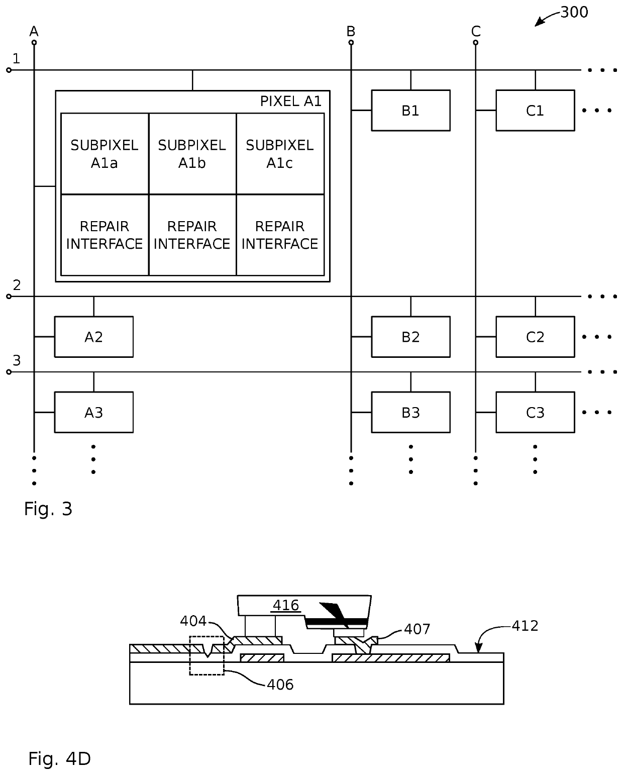
[0035]FIG. 3 is a schematic block diagram depicting a display with emissive element repair interfaces. The display 300 comprises a substrate with a top surface (shown in subsequent figures) and a matrix of electrically conductive control (column and row) lines. For simplicity, only row lines 1, 2, and 3 are shown with colu...


PUM

PropertyMeasurementUnit
threshold voltageaaaaaaaaaa
voltageaaaaaaaaaa
thickaaaaaaaaaa

Abstract

A system and method are provided for repairing an emissive element display. If a defective emissive element is detected in a subpixel, a subpixel repair interface isolates the defective emissive element. The repair interface may be a parallel repair interface with n number of selectively fusible electrically conductive repair nodes, connected in parallel to a control line of the matrix. Alternatively, the repair interface may be a series repair interface with m number of repair nodes, selectively connectable to bypass adjacent (defective) series-connected emissive elements. If the subpixel emissive elements are connected in parallel, and a defective low impedance emissive element is detected, a parallel repair interface fuses open a connection between the defective emissive element and a matrix control line. If the subpixels include series-connected emissive elements, and a high impedance emissive element is detected, a series repair interface forms a connection bypassing the defective emissive element.

Description

RELATED APPLICATIONS[0001]Any and all applications, if any, for which a foreign or domestic priority claim is identified in the Application Data Sheet of the present application are hereby incorporated by reference under 37 CFR 1.57.BACKGROUND OF THE INVENTION1. Field of the Invention[0002]This invention generally relates to display technology and, more particularly, to inorganic micro-light emitting diode (μLED) displays designed with redundancy and repair features.2. Description of the Related Art[0003]A color display is composed of three subpixels that emit light at three wavelengths corresponding to the visible colors red, green, and blue, which is referred to as an RGB display. The RGB components of the pixel are turned on and off in a systematic way to additively produce the colors of the visible spectrum. There are several display types that produce the RGB images in different ways. Liquid crystal displays (LCDs) are the most prevalent technology and they produce RGB images b...

Claims


Application Information

Patent Timeline
Patent Type & Authority Applications(United States)
IPC IPC(8): H01L33/00H01L33/38H01L33/24
CPCH01L33/0093H01L33/38H01L33/24H01L33/0095G09G3/3225G09G2300/0426G09G2330/10G09G2330/12G09G3/3233H01L25/0753
Inventor LEE, JONG-JANSCHUELE, PAUL J.
Owner ELUX INC
Why Eureka
Try Eureka