Refrigerator fan device and ultra-low temperature freezer

a fan device and ultra-low temperature technology, applied in the direction of cooling fluid circulation, domestic cooling devices, lighting and heating devices, etc., can solve the problems of fan tip noise, disturbing noise, and often perceived disturbing noise of fan devices of this kind

a fan device and ultra-low temperature technology, applied in the direction of cooling fluid circulation, domestic cooling devices, lighting and heating devices, etc., can solve the problems of fan tip noise, disturbing noise, and often perceived disturbing noise of fan devices of this kind

US20200158415A1Active Publication Date: 2020-05-21EPPENDORF SE

Image

  • Refrigerator fan device and ultra-low temperature freezer

Examples


Embodiment Construction

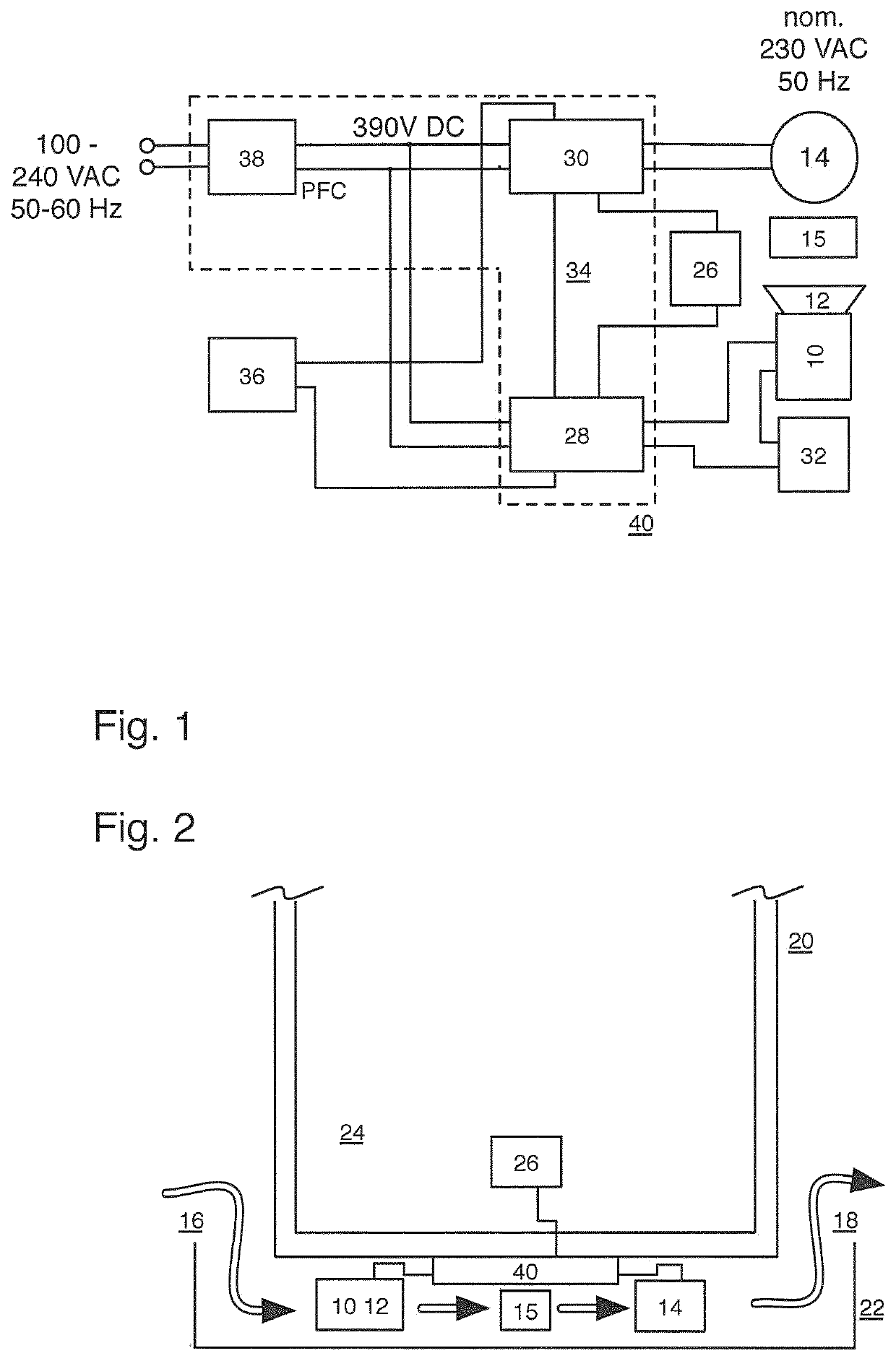
[0021]As the schematic block diagram of FIG. 1 illustrates logically and functionally and as the geometrical illustration of FIG. 2 shows, a fan motor 10 realized as a brushless DC motor and having a fitted fan rotor 12 is placed relative to a heat exchanger (condenser) 15, which dimensioned for ultra-low temperature cooling purposes and includes a refrigerator compressor 14 of a cooling circuit (not shown), in such a manner that a cooling air flow generated by the fan rotor 12, coming from an inlet 16 (suitably covered by a fan grill, a filter or the like in a manner not shown) and conducted toward an outlet 18 can be applied from an ambient air environment of the refrigerator 20 schematically shown in FIG. 2. More precisely, said outlined air-conduction path 16-10-12-15-14-18 is formed in a bottom area 22 of a refrigerator housing of the refrigerator 20, which offers an interior 24 as a used cooling space for receiving cooled goods which, in the embodiment described, can be mainta...


PUM


Abstract

A refrigerator fan device, comprising: a fan motor (10) which has a fan rotor (12) and which can be provided in an air duct between an air inlet (16), a refrigerator heat exchanger (15), and / or a refrigerator compressor (14) and an air outlet (18) on or in a refrigerator housing (20, 22), said fan motor (10) being connectable to a unit of the refrigerator, via electrical supply and / or control lines, wherein the fan motor (10) is realized as a brushless speed-controllable DC motor whose operating speed is or can be controlled as a function of an operating and / or used cooling space temperature signal of, the assigned or assignable refrigerator compressor.

Description

BACKGROUND OF THE INVENTION[0001]The present invention relates to a refrigerator fan device. Furthermore, the present invention relates to an ultra-low temperature refrigerator having such a fan device.[0002]It is generally known from the state of the art for refrigerators, in particular ultra-low temperature (ULT) refrigerators, i.e. refrigerators for a used cooling space at a cooling temperature below −40° C., typically even below −60° C. to as far as −80° C. and below, to be provided with fan devices for heat removal of the process heat produced at the heat exchanger (condenser) in the thermodynamic process and, if required, for cooling the refrigerator compressors employed. These fan devices, which typically have at least one fan motor driving a fan rotor, are suitably provided in an air duct, typically on or in the area of a bottom of a refrigerator housing, and guide air entering through an air inlet across the condenser and the compressors and to an air outlet, thus ensuring ...

Claims


Application Information

Patent Timeline
21 May 2020
Publication
US20200158415A1
IPC
F25D17/06; H02P29/60; F25D17/08; F25D11/02
CPC
F25D2600/06; F25D2317/0666; F25D11/02; F25B2600/112; F25D17/08; F25D17/067; F25D2700/122; F25D2600/02
Inventors
CLARKE, SIMON; MASON, GEORGE