System for measuring residual stress in optical thin films in both transmission and reflection

a technology of transmission and reflection, applied in the direction of measurement devices, force measurement by measuring optical property variation, instruments, etc., can solve the problems of inability to use apparatus and failure to achieve the measurement of residual stress, and achieve the effect of reducing both the purchase cost and the maintenance cos

Active Publication Date: 2020-05-28
FENG CHIA UNIVERSITY
View PDF0 Cites 3 Cited by
  • Summary
  • Abstract
  • Description
  • Claims
  • Application Information

AI Technical Summary

Benefits of technology

[0007]Conventional optical-transmission-type residual stress measuring apparatus cannot be used for completing the measurement of residual stress in an optical film having light reflective property, and conventional optical-reflection-type residual stress measuring apparatus is known failing to achieving the measurement of residual stress in an optical film having transparent or translucent property. In view of that, the present invention discloses a system for measuring residual stress in optical thin films

Problems solved by technology

Conventional optical-transmission-type residual stress measuring apparatus cannot be used for completing the measurement of residual stress in an optical film having light reflective property, and c

Method used


Image

  • System for measuring residual stress in optical thin films in both transmission and reflection
  • System for measuring residual stress in optical thin films in both transmission and reflection
  • System for measuring residual stress in optical thin films in both transmission and reflection

Examples


first embodiment

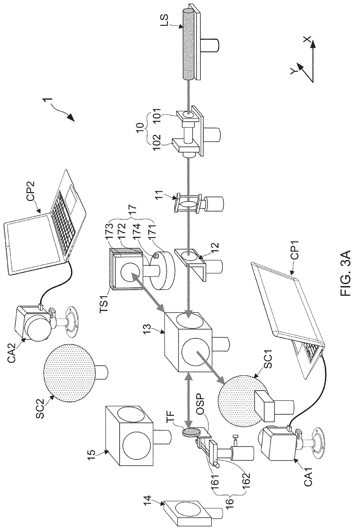
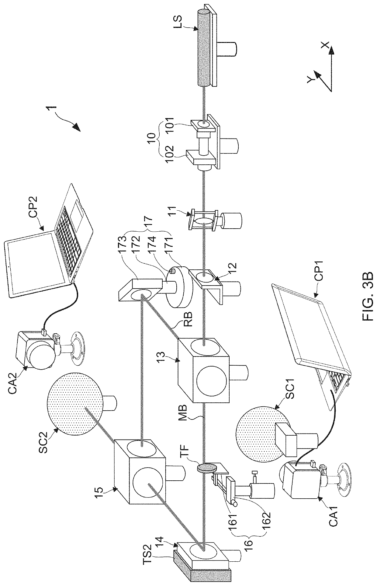
[0057]With reference to FIGS. 3A and 3B, there are provided framework views of a system for measuring residual stress in optical thin films according to the present invention. As FIG. 3A shows, the residual stress measuring system 1 proposed by the present invention comprises: a laser source LS, a spatial filter 10, a collimating lens module 11, an aperture module 12, a first beam splitter module 13, a test plate module 17, a sample carrying module 16, a first screen SC1, a first image capturing module CAL a reference plate 14, a second beam splitter module 15, a second screen SC2, a second image capturing module CA2, a first controlling and processing module CP1, and a second controlling and processing module CP2.

[0058]Following on from the previous descriptions, the laser source is a helium-neon laser device, which is provided herein for emitting a laser beam. Moreover, the spatial filter 10 is configured for receiving the laser beam and subsequently applying a spatial filtering p...

second embodiment

[0064]With reference to FIGS. 4A and 4B, there are provided framework views of the system for measuring residual stress in optical thin films according to the present invention. According to the second embodiment, the residual stress measuring system 2 proposed by the present invention also comprises: a laser source LS, a spatial filter 10, a collimating lens module 11, an aperture module 12, a first beam splitter module 13, a test plate module 17, a sample carrying module 16, a first screen SC1, a first image capturing module CAL a reference plate 14, a second beam splitter module 15, a second screen SC2, a second image capturing module CA2, a first controlling and processing module CP1, and a second controlling and processing module CP2. Differing from the above-described first embodiment, a first linear motion platform PS1 using piezoelectric transducer (PZT) device is arranged in the second embodiment for allowing the test plate 173 to be putted thereon. After the first linear m...


PUM


Abstract

Conventional optical-transmission-type residual stress measuring apparatus cannot be used for completing the measurement of residual stress in an optical film having light reflective property, and conventional optical-reflection-type residual stress measuring apparatus is known failing to achieving the measurement of residual stress in an optical thin film having transparent or translucent property. In view of that, the present invention discloses a system for measuring residual stress in optical thin films, which is able to be utilized for achieving the residual stress measurement of respective optical thin film having transparent or translucent property and that of respective optical thin film having light reflective property. Therefore, it is helpful for largely reducing both the purchase cost and the maintenance cost by only purchasing the residual stress measuring system provided by the present invention instead of simultaneously purchasing the aforesaid two different types of residual stress measuring apparatuses.

Description

BACKGROUND OF THE INVENTION1. Field of the Invention[0001]The present invention relates to the technology field of measurement apparatuses of residual stress in thin film materials, and more particularly to a system for measuring residual stress in optical thin films.2. Description of the Prior Art[0002]Optical film, a dielectric thin film formed on an optical element or a substrate, is adopted for changing transmission characteristics of a light beam through a specific optical effect, such as light reflection, light transmission, light absorption, light scattering, light polarization, and changing the phase of light beam. With the high advancement of optical devices and the popularization of optical products, developments and applications of various optical thin films are becoming more and more important. However, it is found that there is residual stress forming in one optical thin film during the fabrication of the optical thin film on one substrate, such that the fabricated opti...

Claims


Application Information

Patent Timeline
IPC IPC(8): G01L1/24G01B11/16
CPCG01B11/161G01L1/24G01B9/02024G01B9/02027G01B11/2441
Inventor TIEN, CHUEN-LIN
Owner FENG CHIA UNIVERSITY
Why Eureka
Try Eureka