Circuit arrangement for an optical monitoring system and method for optical monitoring
- Summary
- Abstract
- Description
- Claims
- Application Information
AI Technical Summary
Benefits of technology
Problems solved by technology
Method used
Image
Examples
Embodiment Construction
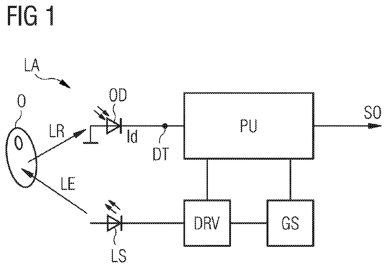
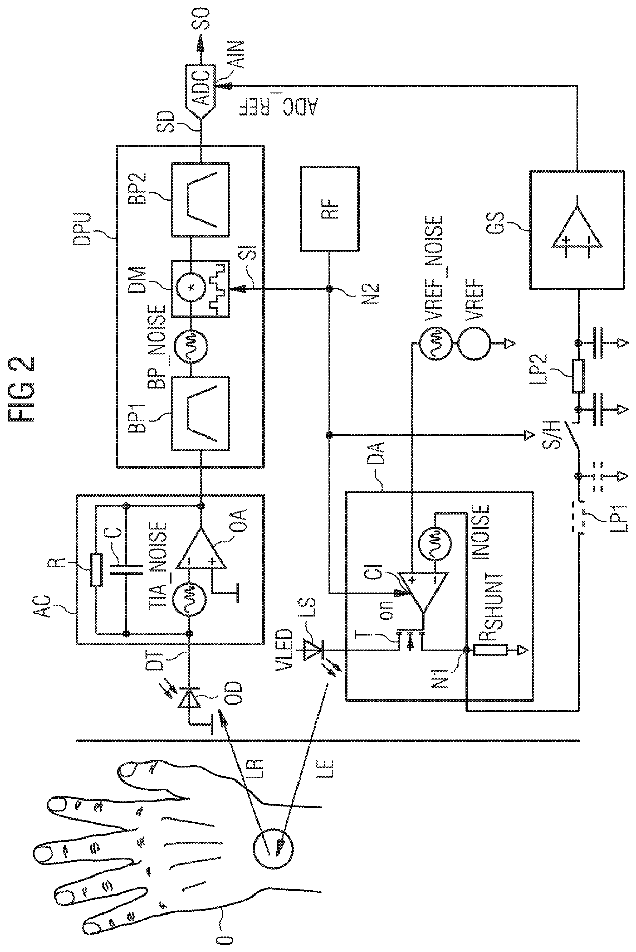
[0041]FIG. 1 shows an exemplary embodiment of a circuit arrangement for an optical monitoring system. The circuit arrangement comprises a driver circuit DRV, a processing unit PU, which is connected to the driver circuit DRV and to a detector terminal DT, and further comprises a gain stage CS, which, at its input side, is connected to the detector terminal DT and which, at its output side, is connected to the processing unit PU. Furthermore, an optical detector OD connected to the detector terminal DT as well as a light source LS connected to the driver circuit DRV are shown in the drawing. The optical detector OD and the light source LS may be comprised by the circuit arrangement. In alternative embodiments the optical detector OD and / or the light source LS are not comprised by circuit arrangement. For example, the circuit arrangement can be integrated as an integrated circuit, IC, e.g. by means of a CMOS process. The integrated circuit, IC, may comprise the optical detector OD as ...
PUM
 Abstract
Description
Claims
Application Information
 - R&D Engineer
- R&D Manager
- IP Professional
- Industry Leading Data Capabilities
- Powerful AI technology
- Patent DNA Extraction
Browse by: Latest US Patents, China's latest patents, Technical Efficacy Thesaurus, Application Domain, Technology Topic, Popular Technical Reports.
© 2024 PatSnap. All rights reserved.Legal|Privacy policy|Modern Slavery Act Transparency Statement|Sitemap|About US| Contact US: help@patsnap.com


