
Therapeutic guidance compute node controller

a compute node controller and therapy technology, applied in the field of therapy guidance compute node controllers, can solve the problems of inability to integrate patient-specific data with 2d specifications from animal tissues, inability to complete treatment and local recurrence, and inability to accurately predict the effect of treatment,

Pending Publication Date: 2020-06-11
VANDERBILT UNIV
View PDF3 Cites 4 Cited by
  • Summary
  • Abstract
  • Description
  • Claims
  • Application Information

AI Technical Summary

Benefits of technology

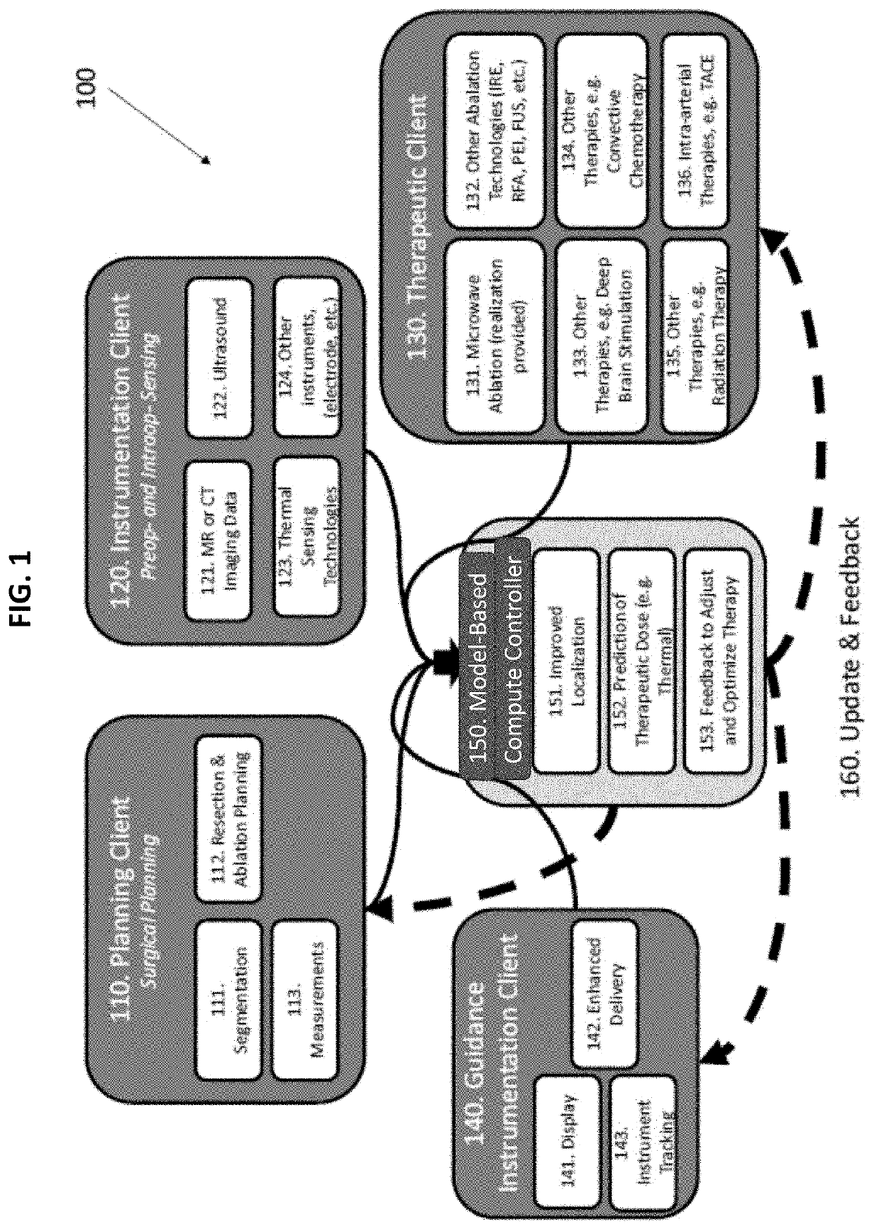
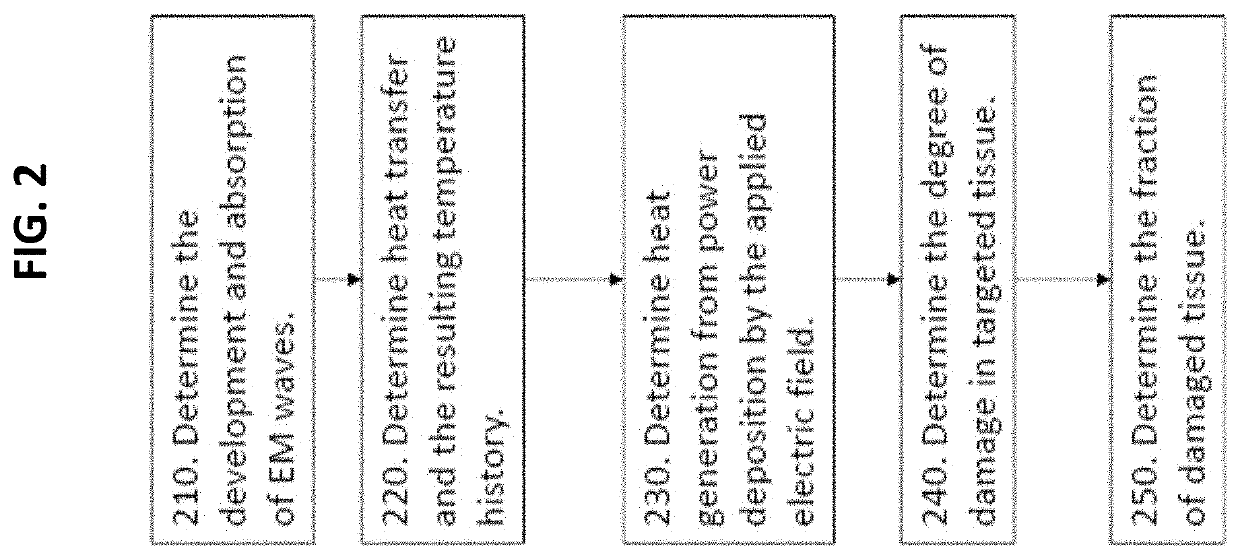
The present patent is about a system and method that can predict and monitor ablation procedures, such as microwave ablation. It uses fat saturation images and deformation correction methodology to create custom microwave ablation bioelectric / biothermal models. This allows for real-time monitoring and guidance during the ablation procedure, improving the accuracy and safety of the procedure. The system includes a processor and memory for storing instructions and a collection of spatially encoded information. The system can also include instruments for collecting information. The technical effects include improved precision and safety during ablation procedures.

Problems solved by technology

As the procedural process inherently targets internal structures, the efficacy of ablation is highly reliant on accurate localization and targeting of these subsurface diseased tissues during a procedure, as inaccurate delivery can lead to incomplete treatment and local recurrence.
However, with these methods, real-time localization, monitoring, and assessment are extremely limited because of challenges with MR-compatibility, availability, and considerable cost.
Additionally, using 2D specifications from animal tissues fails to integrate patient-specific data omits important variables from the procedure, such as geometric, dielectric and thermal properties of the tissue, specific heat, and the rate of blood perfusion when present.
Presently, patient-specific dielectric and thermal properties are unavailable in a clinical setting, even though there is clear variation between patients with the same disease state.
Furthermore, there is often no integration of these 2D predictions with the 3D patient images, placing a burden on the physician to mentally reconstruct and compare complex volumes when planning and performing the procedure.
Physicians cannot accurately predict many of these variables.
For example, physicians often fail to account for soft-tissue deformation that occur from organ mobilization during procedures; these deformations cause substantial registration error and represent a considerable source of error for current procedures.
However, these models still neglect the variation in material properties that can occur between patients.
Additionally, these methods are limited to rigid registration approaches for predicting dose distribution, which neglect soft-tissue deformations.
However, when compared to image-to-physical registration, the EM-iUS approach limits the subsurface information that is provided by the measurements, i.e. US data is the sole source of diseased tissue information.
Additionally, EM-iUS solutions can lose efficacy when ultrasound lesion visualization is compromised, as occurs when targeting lesions in cirrhotic patients or in patients with chemotherapy-induced hyperechogenicity associated with steatosis.
Some other model-based soft-tissue deformation correction approaches have also tried to provide solutions for procedure planning, however such approaches generally have several short-comings.
First, most conventional approaches fail to integrate the other complex variables of procedure planning, including patient-specific data associated with anatomical variations, tissue heterogeneity, tissue perfusion, and tissue properties (e.g. thermal, dielectric, mechanical).
Second, most approaches are implemented through cumbersome add-ons to the procedure with more instruments, in order to provide the needed real-time measurements (e.g. conducting the procedure in an intraoperative magnetic resonance imaging unit to perform real-time thermometry).
Third, these approaches tend to be high-cost, especially for the little additional predictive information which is provided by the approach.

Method used


Image

  • Therapeutic guidance compute node controller
  • Therapeutic guidance compute node controller
  • Therapeutic guidance compute node controller

Examples


Embodiment Construction

[0066]In describing a preferred embodiment of the invention illustrated in the drawings, specific terminology will be resorted to for the sake of clarity. However, the invention is not intended to be limited to the specific terms so selected, and it is to be understood that each specific term includes all technical equivalents that operate in a similar manner to accomplish a similar purpose. Several preferred embodiments of the invention are described for illustrative purposes; it being understood that the invention may be embodied in other forms not specifically shown in the drawings.

[0067]The foregoing description and drawings should be considered as illustrative only of the principles of the invention. The invention is not intended to be limited by the preferred embodiment and may be implemented in a variety of ways that will be clear to one of ordinary skill in the art. Numerous applications of the invention will readily occur to those skilled in the art. Therefore, it is not de...


PUM


Abstract

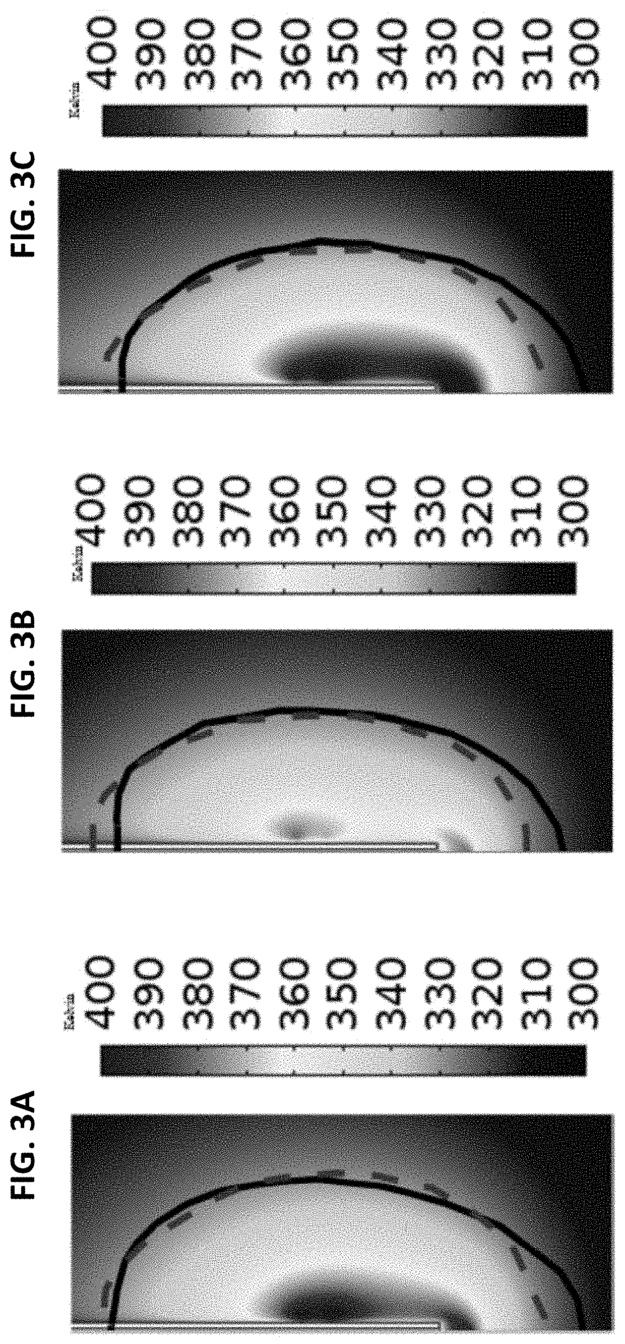
The various examples of the present disclosure are directed towards a multi-physics controller that can predict and monitor ablation procedures. In some examples of the present disclosure, fat saturation images can be used to create custom microwave ablation bioelectric / biothermal models. In some examples of the present disclosure, a deformation correction methodology can be used. Thereby, microwave and mechanics computational models can forecast therapeutic delivery intraoperatively while correcting for deformation.

Description

CROSS-REFERENCE TO RELATED APPLICATIONS[0001]This application claims the benefit of U.S. Provisional App. No. 62 / 777,611, filed Dec. 10, 2018, the entire contents of which are incorporated herein by reference.STATEMENT REGARDING FEDERALLY SPONSORED RESEARCH[0002]This invention was made with government support under NIH Grant No. R01CA162477 awarded by the U.S. Department of Health & Human Services. The government has certain rights in the invention.FIELD OF THE INVENTION[0003]The present disclosure relates to systems and methods for computationally modeling a biophysical process to guide a therapeutic device.BACKGROUND OF THE INVENTION[0004]Loco-regional therapies, such as thermal ablation, have received increased indications for use in neoadjuvant roles, ablation assisted resection, and for the treatment of unresectable hepatic malignancies. While radiofrequency ablation (RFA) is the most common ablative therapy used clinically, it has presented a relatively high local recurrence r...

Claims


Application Information

Patent Timeline
Patent Type & Authority Applications(United States)
IPC IPC(8): A61B34/10A61B18/12A61B18/18G06T7/00G16H80/00G16H30/00
CPCA61B18/1815G16H80/00A61B2034/101A61B2018/00577A61B18/12G16H30/00A61B34/10G06T2207/30104G06T7/0012A61B2034/105A61B2034/104A61B2034/2055A61B34/25A61B2017/00526A61B2017/00716A61B2018/00791A61B2018/00875A61B18/14A61B18/02A61N7/02A61B2018/00529A61B2018/00797A61B2018/00642A61B2018/00803A61B2017/00128A61B2018/00809A61B2018/00613G16H20/40G16H20/10G16H20/30G16H30/20G16H50/50
Inventor MIGA, MICHAELHEISELMAN, JONCOLLINS, JARROD A.
Owner VANDERBILT UNIV
Learn More