Guide tube retainment feature during crimping of guide tubes

a technology of guide tube and retainer, which is applied in the direction of shock absorbers, mechanical equipment, transportation and packaging, etc., can solve the problems of increasing manufacturing costs and not being optimally efficient, and achieve the effect of reducing manufacturing costs

Active Publication Date: 2020-06-11
CONTINENTAL AUTOMOTIVE SYST INC
View PDF0 Cites 3 Cited by
  • Summary
  • Abstract
  • Description
  • Claims
  • Application Information

AI Technical Summary

Benefits of technology

[0008]The present invention is a new crimping process for an air spring assembly, which does not change cycle time, and reduces manufacturing cost because of the elimination of a secondary operation, or secondary cri...

Problems solved by technology

However, this additional crimping process typically involves separate tooling, a separate manufacturing pro...

Method used


Image

  • Guide tube retainment feature during crimping of guide tubes
  • Guide tube retainment feature during crimping of guide tubes
  • Guide tube retainment feature during crimping of guide tubes

Examples


Embodiment Construction

[0028]The following description of the preferred embodiment(s) is merely exemplary in nature and is in no way intended to limit the invention, its application, or uses.

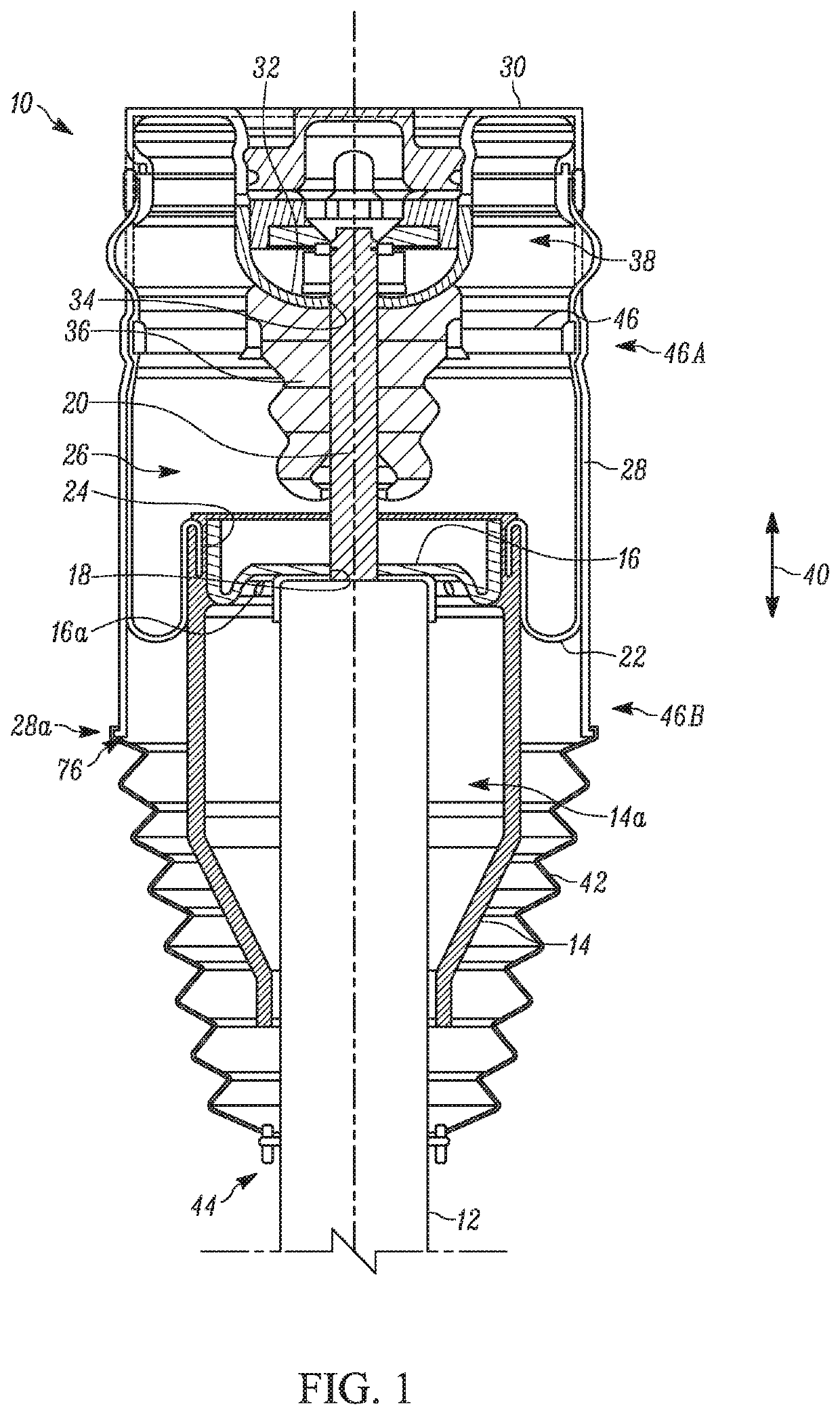
[0029]An air spring assembly for a vehicle, which has undergone a crimping process according to the present invention is shown in FIG. 1, generally at 10. The air spring assembly 10 includes a damper body 12, and surrounding a portion of the damper body 12 is an outer piston 14. The outer piston 14 is connected to an inner piston 16, which is connected to the damper body 12 as shown. The inner piston 16 includes an aperture 18, and extending through the aperture 18 is a damper rod 20. The air spring assembly 10 also includes a bellow 22, which is flexible and able to change shape as the pistons 14,16 are moved relative to the damper rod 20. A free end 24 of the bellow 22 is clamped between portions of the outer piston 14, connecting the bellow 22 to the outer piston 14.

[0030]The bellow 22 includes a cavity, shown gene...


PUM

PropertyMeasurementUnit
Forceaaaaaaaaaa

Abstract

A method for making an air spring assembly, including the steps of providing a bellow, a support ring, and a guide tube. The support ring is positioned relative to a bellow adapter such that a portion of the bellow adapter extends through the support ring. The bellow is then positioned such that a portion of the bellow extends over the support ring and a portion of the bellow adapter. The guide tube is then positioned relative to the bellow and the support ring, such that a portion of the bellow extends into the guide tube and the guide tube is supported by the bellow adapter, and a portion of the guide tube is supported by a ridge support fixture. The first clamp and second clamp are then moved towards the guide tube, applying force to the guide tube, simultaneously forming a first crimp and a second crimp.

Description

CROSS-REFERENCE TO RELATED APPLICATIONS[0001]This application claims the benefit of Provisional Application 62 / 776,307, filed Dec. 6, 2018. The disclosure of the above application is incorporated herein by reference.FIELD OF THE INVENTION[0002]The invention relates generally to an air spring assembly which includes at least two crimp areas which are formed simultaneously during manufacturing.BACKGROUND OF THE INVENTION[0003]Suspension systems for automotive vehicles provide vehicle passengers with a more comfortable ride. Air suspension systems utilize air springs, rather than traditional coil springs. Air suspension systems provide different suspension qualities that may be preferable in some vehicles to traditional coil spring suspensions.[0004]A conventional air spring is a device that is arranged between a vehicle body and chassis. The typical air spring has at least one working space, or cavity that is filled with compressed air. Air spring pistons typically seal the air chambe...

Claims


Application Information

Patent Timeline
IPC IPC(8): B21D39/04F16L13/14
CPCB60G11/27B21D39/048B21D39/046F16L13/141F16L2013/145B60G15/14B60G2202/152B60G2202/314B60G2204/126B60G2204/1262B60G2204/4308B60G2206/42B60G2206/91F16F9/057F16F2226/04
Inventor JERISK, JOSEPH G.
Owner CONTINENTAL AUTOMOTIVE SYST INC
Why Eureka
Try Eureka