Engine System

a technology of engine system and engine, applied in the direction of electrical control, exhaust treatment electric control, hybrid vehicles, etc., can solve the problems of not being able to guarantee, need high temperatures to work, and affecting health and the environment, so as to avoid unnecessary use of the engine and reduce emissions.

Active Publication Date: 2020-06-11
J C BAMFORD EXCAVATORS LTD
View PDF0 Cites 2 Cited by
  • Summary
  • Abstract
  • Description
  • Claims
  • Application Information

AI Technical Summary

Benefits of technology

[0041]In other words, where a low load demand has been placed on the vehicle, the engine system is configured to drive the driveline in the electric mode and so not start the engine. The engine will therefore only be started when the load demands are great enough to necessitate this. Accordingly, unnecessary use of the engine is avoided.
[0042]Additionally, when the engine is running at a light load demand, exhaust gases from the engine will be at a relatively low temperature and so the temperature of the after-treatment arrangement will not be optimal for minimising emissions. Accordingly, running in the electric mode avoids the engine system running in non-clean modes.

Problems solved by technology

Whilst these engines can be efficient and cost effective they emit exhaust pollutants (hydrocarbons, nitrogen oxides and particulate matter), which can be detrimental to health and to the environment.
Passive filters use a catalyst to remove accumulations, but need high temperatures to work.
This cannot be guaranteed for off-highway applications, because the engine may spend a significant time idling, such that sufficient temperatures may not be achieved passively.
Disadvantages of active DPFs include an increased specific fuel consumption.
On the downside, there is a risk that excess injection of urea reductant, or that ammonia resident in the SCR catalyst at lower temperatures and released as the catalyst heats, causes unreacted ammonia to be emitted from the SCR into the atmosphere.

Method used


Image

  • Engine System
  • Engine System
  • Engine System

Examples


Embodiment Construction

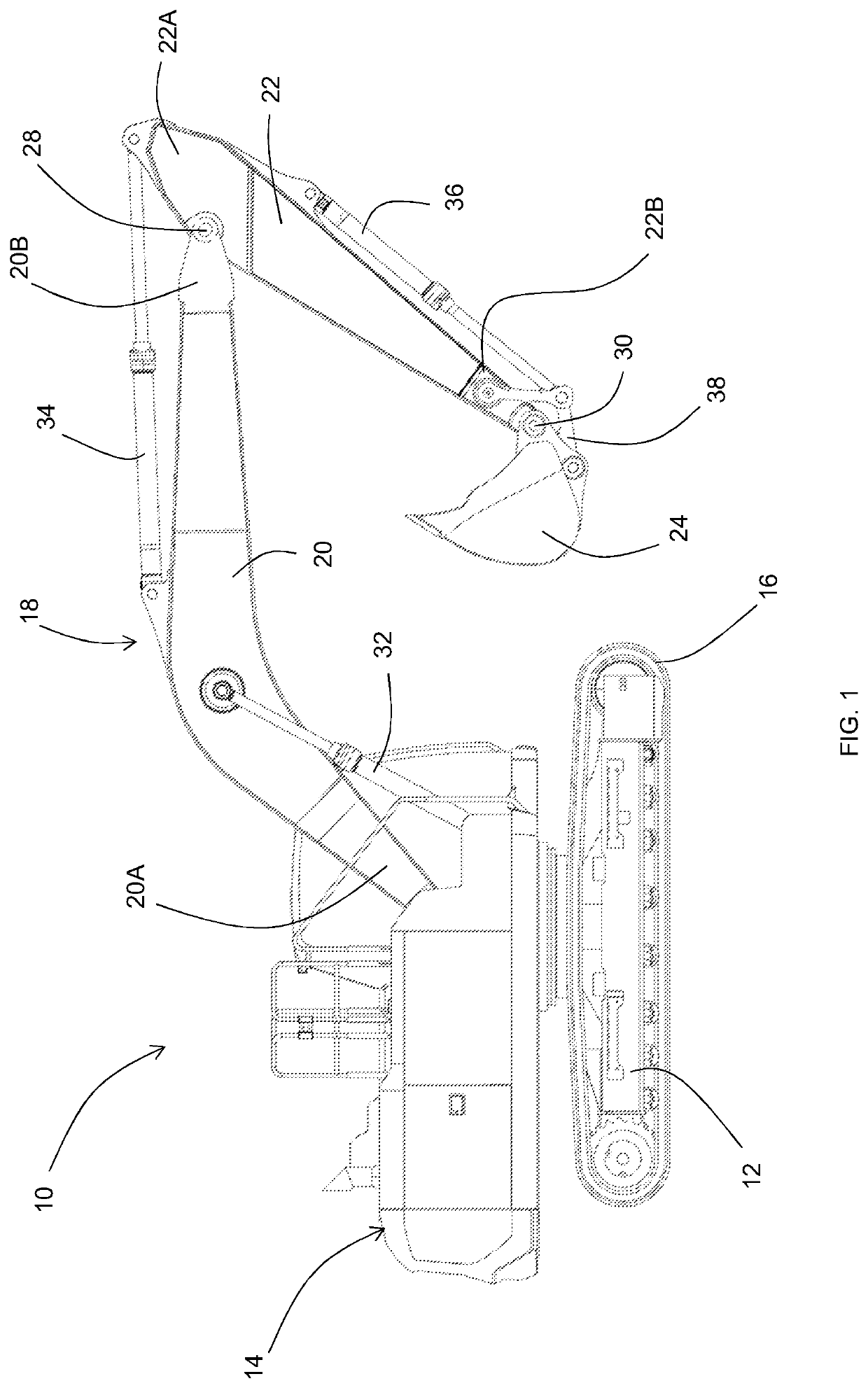
[0082]With reference to FIG. 1 there is shown an off-highway vehicle 10, e.g. an excavator, including a chassis 12 and a superstructure 14 carrying an operator station from which an operator can control the vehicle. The superstructure 14 is mounted on the chassis 12. Ground engaging transport means in the form of a pair of tracks 16 are provided on the chassis 12 to move the machine over the ground.

[0083]Off-highway vehicles are for example those used in construction industries (e.g. backhoe loaders, slew excavators, telescopic handlers, forklifts, skid-steer loaders, dump trucks, bulldozers, graders), agricultural industries (tractors, combine harvesters, self-propelled harvesters and sprayers), quarrying (e.g. loading shovels, aggregate crushing equipment), and forestry (timber harvesters, feller bunchers).

[0084]Attached to the vehicle superstructure 14 is an arm assembly 18, the arm assembly includes a first arm in the form of a boom 20, a second arm in the form of a dipper 22 an...


PUM


Abstract

An engine system for an off-highway vehicle, comprising: a diesel engine configured to drive a driveline of the vehicle; an after-treatment arrangement configured to reduce emissions from the engine system; an after-treatment heating element configured to raise an operating temperature of the after-treatment arrangement; an electric energy storage device; and a controller configured to direct energy from the electric energy storage device to the after-treatment heating element in order to raise the operating temperature of the after-treatment arrangement.

Description

FIELD OF THE INVENTION[0001]The present disclosure relates to an engine system and an off-highway vehicle comprising said engine system. More particularly, though not exclusively, the present disclosure relates to an engine system configured to reduce emissions from an off-highway vehicle.BACKGROUND OF THE INVENTION[0002]Off-highway vehicles use, almost exclusively, combustion engines to provide the energy and power required for operation. Whilst these engines can be efficient and cost effective they emit exhaust pollutants (hydrocarbons, nitrogen oxides and particulate matter), which can be detrimental to health and to the environment.[0003]Various abatement technologies are known for diesel engines, which may be used alone or in combinations, to reduce these harmful emissions. These technologies include the following:[0004]Diesel particulate filters (DPF) are provided to remove particulate matter from engine exhausts. As the particulate matter may accumulate in the filter causing ...

Claims


Application Information

Patent Timeline
Patent Type & Authority Applications(United States)
IPC IPC(8): F02D41/02F01N3/20F02N19/02B60L1/08
CPCB60L1/08F02D41/0255F01N3/2013F02N19/02F02D2041/026F01N3/027F01N2590/11F01N2590/08F01N3/206F01N9/00F01N2900/1602Y02T10/40Y02A50/20Y02T10/12B60W10/26B60W20/16F01N2240/16F02N19/10B60W20/13
Inventor TOLLEY, ALAN
Owner J C BAMFORD EXCAVATORS LTD
Why Eureka
Try Eureka