Brush assembly

Active Publication Date: 2020-06-11
SIEMENS GAMESA RENEWABLE ENERGY AS
View PDF0 Cites 0 Cited by
  • Summary
  • Abstract
  • Description
  • Claims
  • Application Information

AI Technical Summary

Benefits of technology

[0026]FIG. 1 is a simplified representation of a direct

Problems solved by technology

However, as generator designs become more compact, it is becoming increasingly difficult to incorporate the conventional brushes in the LPS in such a way that the brush assemblies can also be accessed for regular maintenance, since the carbon/graphite brushes wear down over time and need to be exchanged at regular intervals

Method used


Image

  • Brush assembly
  • Brush assembly
  • Brush assembly

Examples


Example

[0027]FIG. 2 shows a first embodiment of the inventive brush assembly;

Example

[0028]FIG. 3 shows a second embodiment of the inventive brush assembly;

[0029]FIG. 4 shows a partial cross-section of the embodiment of FIG. 3;

[0030]FIG. 5 shows an embodiment of the inventive brush assembly in place in a first environment;

[0031]FIG. 6 shows a cross-section of the embodiment of FIG. 5;

[0032]FIG. 7 shows an embodiment of the inventive brush assembly in place in a first environment; and

[0033]FIG. 8 shows an embodiment of the inventive brush assembly in place in a first environment.

[0034]In the diagrams, like numbers refer to like objects throughout. Objects in the diagrams are not necessarily drawn to scale.

DETAILED DESCRIPTION

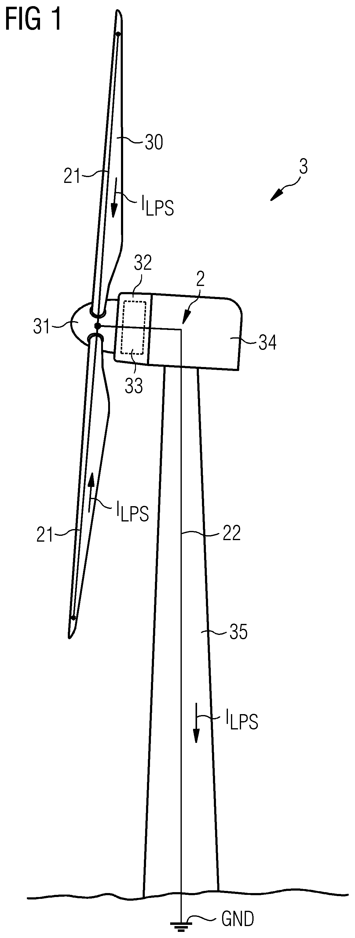
[0035]FIG. 1 is a simplified diagram of a direct-drive wind turbine 3 and its LPS 2. The aerodynamic rotor of the wind turbine comprises the rotor blades 30 mounted to the hub 31. The outer rotor 32 of the generator can be enclosed in a housing that rotates as one with the outer rotor 32. The diagram also shows a stationary canopy 34 or nacelle 3...


PUM


Abstract

Provided is a brush assembly for transferring lightning current between a first structure and a second structure, which brush assembly includes a holder realized for mounting to one of the two structures; a recess formed in the holder, which recess is shaped to accommodate a brush and to expose a first brush face; and a first displacement means arranged to move the first exposed brush face against a surface of the first structure; and wherein the recess is shaped to also expose a second brush face, and the brush assembly further includes a second displacement means arranged to move the second exposed brush face against a surface of the second structure. Further provided is a lightning protection circuit of a wind turbine; and a wind turbine.

Description

CROSS-REFERENCE TO RELATED APPLICATIONS[0001]This application claims priority to EP Application No. 182107840.9, having a filing date of Dec. 6, 2019, the entire contents of which are hereby incorporated by reference.FIELD OF TECHNOLOGY[0002]The following relates to a brush assembly, a lightning protection circuit, and a wind turbine.BACKGROUND[0003]Because of its height and generally exposed location, a wind turbine may receive frequent lightning strikes and must be equipped with a reliable lightning protection system (LPS) to prevent damage to its rotor blades, its electrical components, and its structural components. A wind turbine rotor blade is normally provided with one or more receptors on its outer surface that act to attract a lightning strike. Each receptor is connected to a download cable or “down conductor” extending through the blade interior. A down conductor usually extends from near the thin blade tip (at the outermost end of the blade) to the circular root (at the i...

Claims


Application Information

Patent Timeline
IPC IPC(8): F03D80/30
CPCF03D80/30H01R39/26H01R39/381H01R39/38H01R39/383H01R39/64H02G13/40Y02E10/72H01R39/40
Inventor MICHAELSEN, CLAUSOLSEN, KAJ
Owner SIEMENS GAMESA RENEWABLE ENERGY AS
Why Eureka
Try Eureka