Eureka AIR delivers breakthrough ideas for toughest innovation challenges, trusted by R&D personnel around the world.

Imaging apparatus and imaging method

a technology of imaging apparatus and imaging method, which is applied in the direction of camera filters, radioation control devices, instruments, etc., can solve the problem of the upper limit of the charge that can be accumulated by the photoelectric conversion element, and achieve the effect of wide dynamic range, minimum motion blur, and wide dynamic rang

Active Publication Date: 2020-06-11
SONY CORP
View PDF16 Cites 11 Cited by
  • Summary
  • Abstract
  • Description
  • Claims
  • Application Information

AI Technical Summary

Benefits of technology

The present technology allows for imaging with a wide dynamic range and minimal motion blur by using a polarization element and polarization pixels with different sensitivity levels. Gain adjustment is performed based on the sensitivity levels, and image composition is carried out using the gain-adjusted image signals.

Problems solved by technology

However, the amount of charges that can be accumulated by photoelectric conversion element has an upper limit.

Method used


Image

  • Imaging apparatus and imaging method
  • Imaging apparatus and imaging method
  • Imaging apparatus and imaging method

Examples


application examples

4. APPLICATION EXAMPLES

[0089]The technology of the present disclosure may be applied to diverse products. For example, the technology may be implemented as an apparatus to be attached not only on information processing terminals but also on such mobile objects as automobiles, electric vehicles, hybrid electric vehicles, motorcycles, bicycles, personal mobility devices, aircraft, drones, ships, robots, construction equipment, and agricultural machinery (tractors).

[0090]FIG. 18 is a block diagram depicting an example of schematic configuration of a vehicle control system 7000 as an example of a mobile body control system to which the technology according to an embodiment of the present disclosure can be applied. The vehicle control system 7000 includes a plurality of electronic control units connected to each other via a communication network 7010. In the example depicted in FIG. 18, the vehicle control system 7000 includes a driving system control unit 7100, a body system control uni...


PUM


Abstract

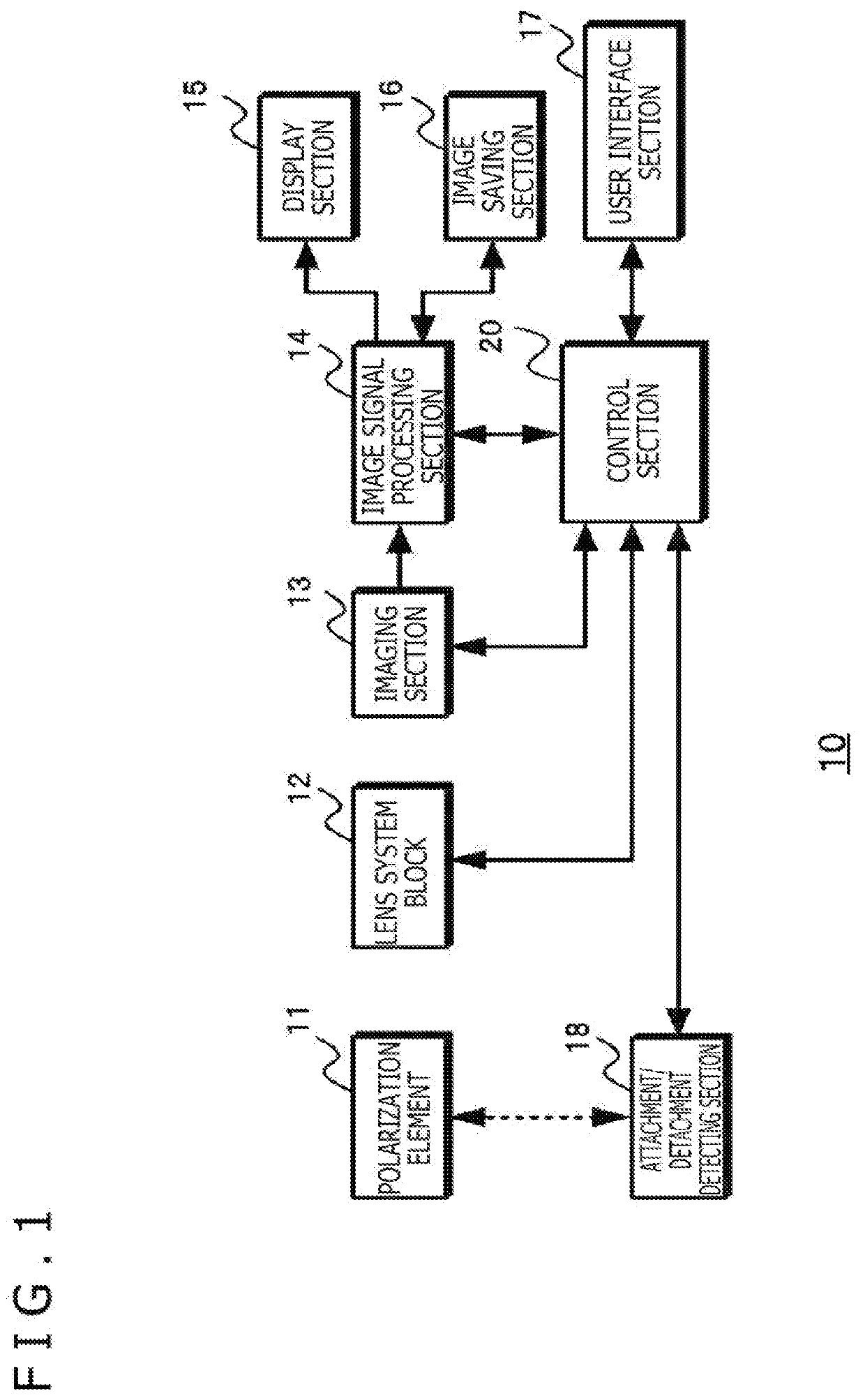
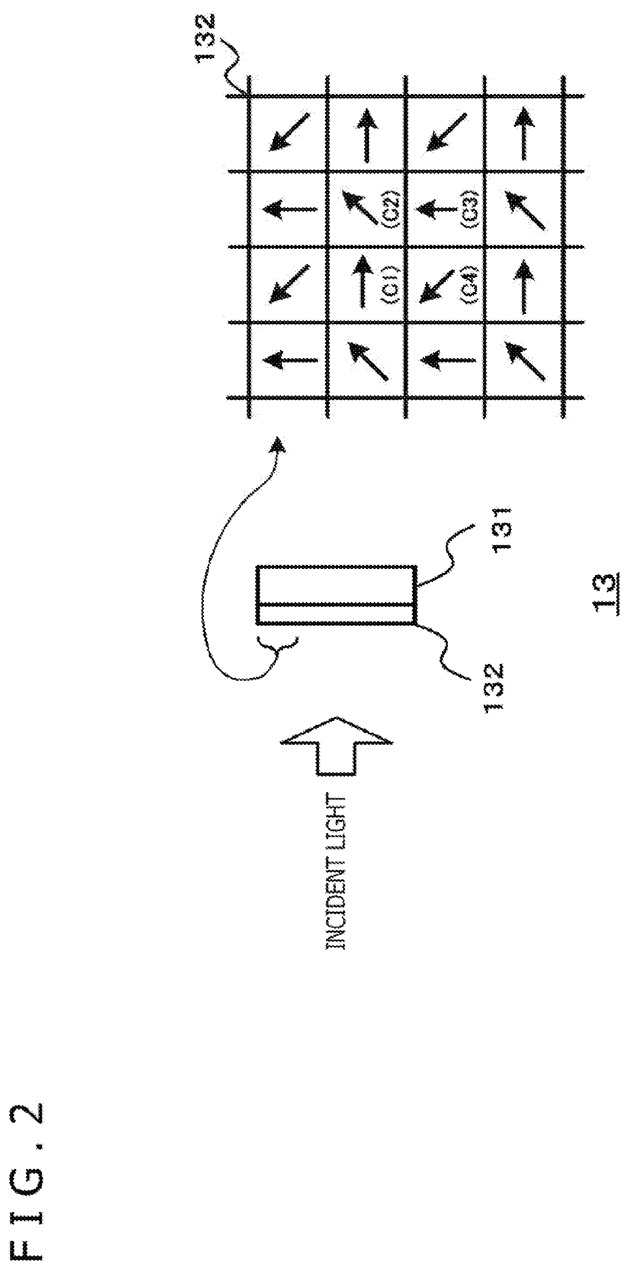
An imaging section 13 allows multiple pixels generating a pixel signal based on incident light to act as polarization pixels each having one of multiple polarizing directions. A polarization element 11, attached on the side of the incidence plane side of the imaging section 13, causes linearly polarized light to enter the imaging section 13. A control section 20, for example, controls a sensitivity detecting section to detect a sensitivity level in each of the polarizing directions of the polarization pixels in the imaging section 13. An image signal processing section 14 performs gain adjustment on the polarization pixels on the basis of the sensitivity level detected in each of the polarizing directions by the sensitivity detecting section, and carries out image composition using the gain-adjusted image signals to generate a captured image having wide dynamic range with minimum motion blur.

Description

TECHNICAL FIELD[0001]The present technology relates to an imaging apparatus and an imaging method for capturing images having dynamic range with minimum motion blur.BACKGROUND ART[0002]Imaging apparatuses use solid-state imaging devices such as CMOS (Complementary Metal Oxide Semiconductor) image sensors or CCD (Charge Coupled Device) image sensors. These types of solid-state imaging devices perform photoelectric conversion to accumulate electric charges reflecting the amount of incident light in order to output an electric signal representing the accumulated charges. However, the amount of charges that can be accumulated by photoelectric conversion element has an upper limit. Given an amount of light exceeding a certain level, the amount of accumulated charges reaches a saturation level. A target object region subjected to a luminance level higher than the certain level is brought to the saturation level in a phenomenon known as overexposure and appears overly bright. Under these c...

Claims


Application Information

Patent Timeline
IPC IPC(8): H01L27/146G02B5/30H04N5/232
CPCH01L27/14605G02B5/30H04N5/23238H04N5/2254H01L27/14645G03B11/00G03B15/00H04N7/18G02B5/201H04N23/55H04N23/611H04N23/667H04N23/741H04N23/75H04N23/698
Inventor MITANI, HITOSHIWAKAZONO, MASAFUMI
Owner SONY CORP
Why Eureka
Eureka Blog
Learn More