Skull-Mounted Drug and Pressure Sensor

a pressure sensor and ommaya technology, applied in the field of implantable pumps, can solve problems such as improper drug delivery, catheter lesions, and infections of the ommaya reservoir, and achieve the effects of improving the safety and safety of patients, reducing the risk of infection, and improving the safety of patients

Pending Publication Date: 2020-06-25
COGNOS THERAPEUTICS INC
View PDF0 Cites 2 Cited by
  • Summary
  • Abstract
  • Description
  • Claims
  • Application Information

AI Technical Summary

Benefits of technology

[0009]The SOS provides the ability to measure the concentration of a drug in the cerebro-spinal fluid (CSF) at the site of delivery and communicate the data to an external device or to the pump. This significant enhancement over existing Ommaya reservoir technology allows the physician to monitor drug diffusion away from the delivery site, thereby verifying CSF patency and proper placement of the ventricularly placed sensor and drug delivery catheter. The SOS also does not have a reservoir for holding CSF fluid or provide access to CSF fluid via a port as an Ommaya port does unless it is the third embodiment above that is connected to the PCU or the SPS in the fourth embodiment above.

Problems solved by technology

However, the major risks associated with the use of the Ommaya reservoir involves infections and complications due to malposition or malfunction of the device.
In addition, there can be blockage or leakage of the catheter, which can lead to improper drug delivery and development of lesions along the catheter.
The use of Ommaya to deliver chemotherapy drugs by a bolus injection into the brain usually leads to toxic levels of the chemotherapy drug immediately following delivery, a short interval of drug concentration within the therapeutic range followed by long periods of sub-therapeutic drug concentration which could accelerate the development of drug resistance.
It is well known that chemotherapy into the brain also can lead to elevated brain CSF pressure and hydrocephalus if not addressed.

Method used


Image

  • Skull-Mounted Drug and Pressure Sensor
  • Skull-Mounted Drug and Pressure Sensor
  • Skull-Mounted Drug and Pressure Sensor

Examples


fourth embodiment

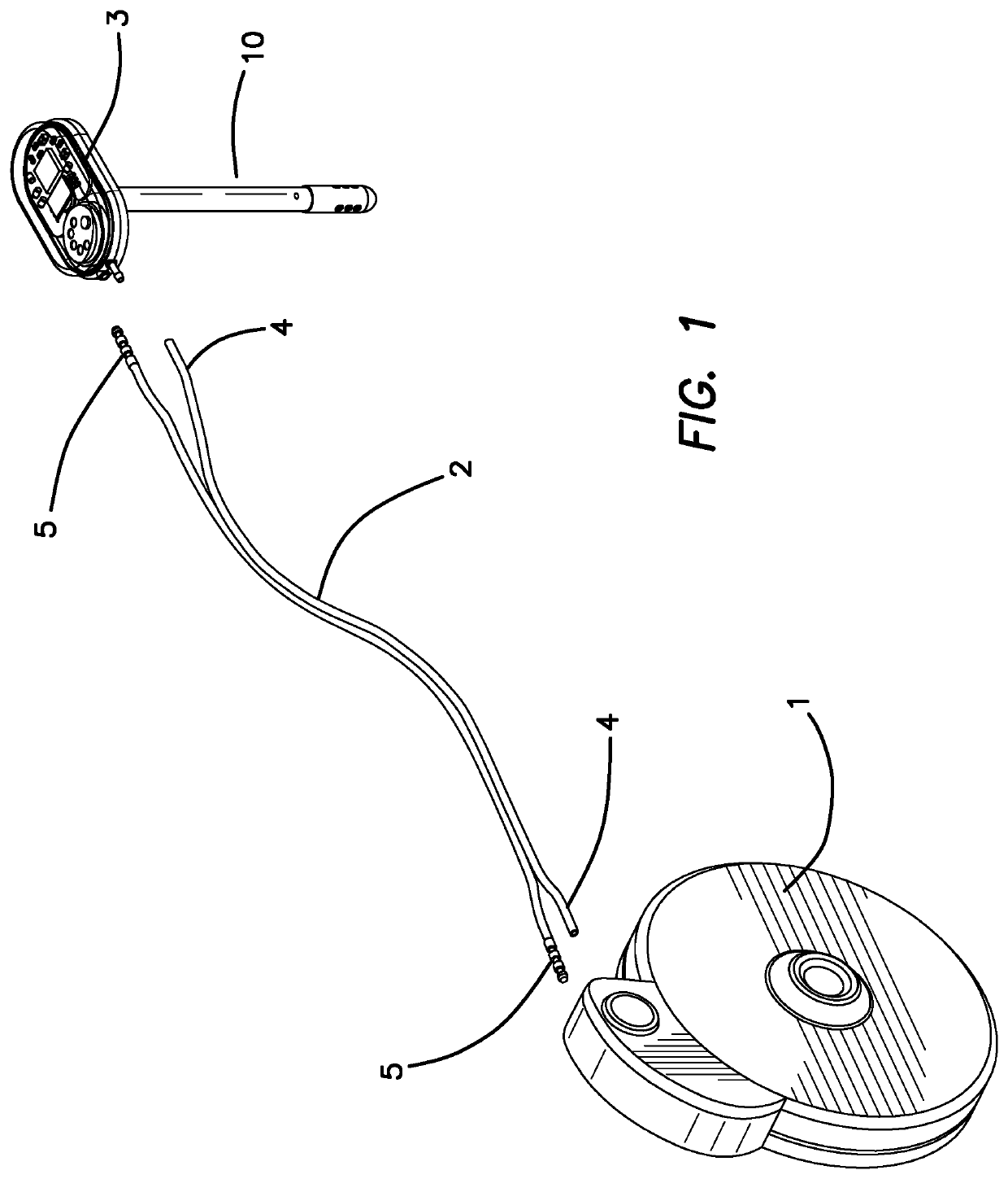
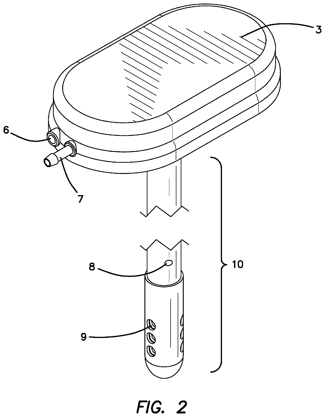
[0038]FIG. 1 illustrates perspective view of the ISP 1, the SOS 3, a ventricular catheter 10 for insertion into the brain and a dual lumen drug supply catheter 2 which connects the pump 1 to the SOS 3. The dual lumen catheter includes one lumen 4 for drug delivery and a second lumen 5 for the wires necessary for bidirectional communication between the SOS 3 and the pump 1. The drug delivery catheter lumen 4 connects to the SOS through port 7 and the electronics wires 5 connect via pass through port 6 as illustrated in FIG. 2. A drug or multiple drugs will be provided through catheter lumen 4 coming from an implantable pump 1 or an external pump (not shown) through a pump reservoir (not shown), or through the ventricular access port 30 in the fourth embodiment in FIGS. 15-16, and thence via ventricular catheter 10 into the ventricle emanating from the drug delivery port 8. The CSF / drug sensing chamber 21 shown in FIG. 6 is in fluid communication with the CSF via holes 9 in FIG. 2. Th...

first embodiment

[0042]FIG. 8 is a block diagram of the power, communication and fluid systems for the ISP 1, catheter system and the SOS in the The ISP 1 and SOS 3 illustrated here have distinct functions. The SOS 3 is designed to provide the essential functions for optical sensing and capturing the sensed information. It also houses the drug-delivery channel 22. The ISP 1 is the source of the drug, the wireless communication system, the drug pump, the power, the main computing and analysis electronics and the software. The diagram labels the main components of the ISP 1, the catheter 2, ventricular catheter 10 and the SOS 3. The wired connector in catheter 2 is connected to the electrical connector tips 4 in FIG. 1 on each end the fluid path in catheter 2 illustrated with a white line. The clear line is the drug delivery lumen 4 which is connected to the ISP and through connector 7 to the SOS 3. The dotted lines around the ISP 1 and SOS 3 illustrate the perimeter of each device. ISP 1 includes a ...

third embodiment

[0054]The embedded micro-controller and Bluetooth controller 52 in the third embodiment provide the bidirectional data communication, data measurement schedule and data storage. The internal button lithium battery 54 provides the necessary operating power. To conserve energy, the electronics hardware 50, 52 will spend the majority of the time in “sleep mode”.

[0055]Since the absorption spectra of most drugs features at least one prominent peak, the UV / VIS LEDs frequencies can be selected to cover optionally one or more leading edges of selected peaks one or more major peak maxima, optionally one or more trailing peak edges and a neutral reference—where absorption does not change with drug concentration—over the drug specific frequencies range.

[0056]The optical sensor has one or more LEDs depending on the requirements of a predetermined analysis complexity. For more flexibility and for general applications the number of LEDs can be increased to cover a wider range of wavelengths and s...


PUM


Abstract

A skull-mounted drug and pressure sensor (SOS), a smart pump (ISP) electrically coupled to the SOS and a drug delivery and communications catheter communicating the SOS with the ISP are combined for a first embodiment. A skull-mounted (SOS), a metronomic biofeedback pump (MBP) electrically coupled to the SOS and a drug delivery and communications catheter having a sending and receiving optical fiber communicating the SOS with the MBP are combined for a second embodiment. A third embodiment combines a (SOS), an implantable power and communication unit (PCU) electrically coupled to the SOS, and a drug delivery and communications catheter for communicating the SOS with the PCU and for communicating the exterior source of the drug to the SOS. A fourth embodiment combines a ventricular catheter with a CSF accessible chamber and drug delivery port; and an implantable stand-alone skull-mounted drug and pressure sensor (SPS).

Description

RELATED APPLICATIONS[0001]The present application is a divisional of U.S. patent application Ser. No. 15 / 594,251, filed on May 12, 2017, which in turn is related to U.S. Provisional Patent Application, Ser. No. 62 / 336,446, filed on May 13, 2016, which are each incorporated herein by reference and to which priority is claimed pursuant to 35 USC 119.BACKGROUNDField of the Technology[0002]The invention relates to the field of implantable pumps used in the treatment of brain cancers and neurological disease. It also relates to a skull-mounted drug and pressure sensor (SOS) that has a built-in optical sensor to detect drugs in a chamber built into a catheter that extends from a skull-mounted body of the SOS into the brain.Description of the Prior Art[0003]An Ommaya reservoir is an intraventricular catheter system that was originally invented in 1963 by Ayub K. Ommaya, a Pakistani neurosurgeon and that can be used for the aspiration of cerebrospinal fluid or for the delivery of drugs (e.g...

Claims


Application Information

Patent Timeline
Patent Type & Authority Applications(United States)
IPC IPC(8): A61B5/00A61M5/142A61B5/03A61B5/1459
CPCA61M5/142A61M5/14A61B2562/0233A61B2090/064A61B5/6868A61B5/031A61B5/0031A61M1/0001A61M27/006A61B5/1459A61B5/01A61B5/4839A61B5/03A61M1/60
Inventor SHACHAR, YEHOSHUACHEN, THOMASLOBL, THOMAS J.BRYDLE, JEFFREY A.GONZALEZ, JUAN R.INDRAVUDH, VIROTEMEROT, CHRISTIANSCHWARTZ, ALLAN R.SRISATHAPAT, CHAD
Owner COGNOS THERAPEUTICS INC
Why Eureka
Try Eureka