Electromechanical brake assist system

a technology of electronic brakes and assist systems, applied in the direction of brake systems, vehicle components, vehicle design optimisation, etc., can solve the problems of comparatively high cost of solution, and achieve the effect of simplifying the brake assist system, simplifying the structure of the control rod, and facilitating assembly

Active Publication Date: 2020-07-23
ROBERT BOSCH GMBH
View PDF8 Cites 0 Cited by
  • Summary
  • Abstract
  • Description
  • Claims
  • Application Information

AI Technical Summary

Benefits of technology

The present invention simplifies the brake assist system by simplifying the structure of the control rod to facilitate assembly, making it faster and more economical. This is achieved by realizing an assist system with a control rod that can be used for a variety of vehicles by simply modifying the head of the control rod based on the vehicle type. This method of realization and assembly is simple and cost-effective.

Problems solved by technology

This solution is comparatively costly because of the production of the threads and the time required for assembly.

Method used


Image

  • Electromechanical brake assist system
  • Electromechanical brake assist system
  • Electromechanical brake assist system

Examples


Embodiment Construction

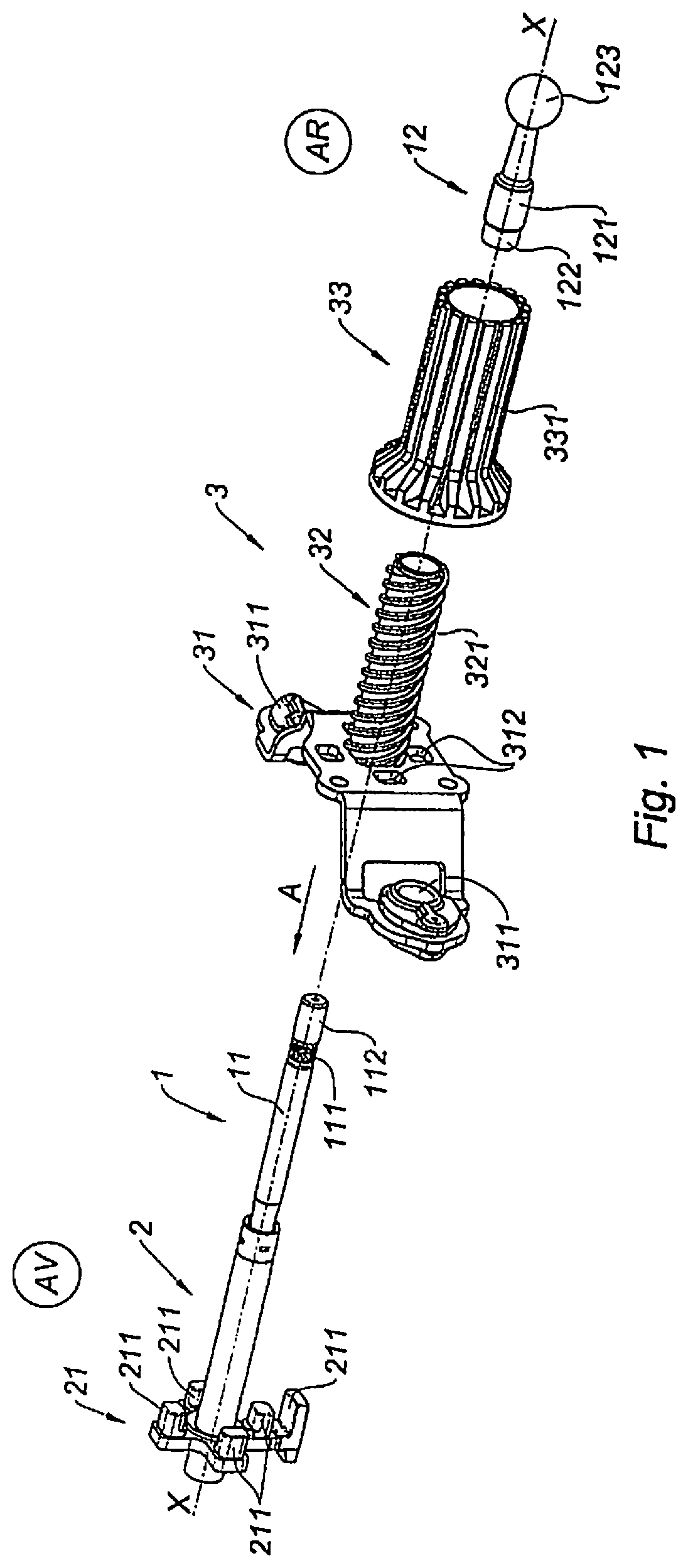
[0026]To simplify the description, the front (AV) is the left side of the xx axis of FIG. 1 and the rear (AR) is the right side.

[0027]The brake assist system according to the present invention, of which only certain elements needed for the description are shown, appears in the exploded view of FIG. 1, composed of a master cylinder (for example, a tandem master cylinder) supplying one or two brake circuits with pressurized brake fluid. The master cylinder is controlled from the brake pedal by a kinematic chain encompassing an actuator in the form of an electric motor, providing, by itself or together with the thrust from the pedal, the force exerted on the primary piston of the master cylinder.

[0028]Beginning with the brake pedal, the kinematic chain aligned along line of action xx consists of a rod connected to the pedal and transmitting its movement to control rod 1, which is itself connected to plunger piston 2, to receive the additional helper thrust for acting directly on the ma...


PUM


Abstract

An electromechanical brake assist system driven by an electric motor cooperating with a master cylinder and having, along the axis of actuation, a helper piston in the shape of an axial sleeve solidly connected with a guide bracket and having a threaded surface. A nut, fixed in translation but free to rotate, has interior threads that complement those of the helper piston, which it receives, and exterior teeth that cooperate with the drive motor. A plunger piston carries a drive base so it can be pushed by the piston. Its other extremity is connected to the control rod, formed from a body and a head. The body has a crimping area and the head has a sleeve with an extremity that can be crimped along the crimping area.

Description

FIELD[0001]The present invention relates to an electromechanical brake assist system driven by an electric motor cooperating with a master cylinder and having, along the axis of actuation:[0002]a helper piston in the shape of an axial sleeve solidly connected with a rotating guide bracket for guidance in translation, the sleeve having a threaded outside surface that cooperates with[0003]a nut, fixed in translation but free to rotate, having interior threads that complement those on the helper piston, which it receives, and having on its exterior a gear connected to the electric drive motor,[0004]a plunger piston having at its front extremity a drive base that can be pushed by the helper piston and at its back extremity a connection to the control rod,[0005]wherein the control rod is formed from a body one of whose extremities is connected to the plunger piston and the other to the head of the control rod.BACKGROUND INFORMATION[0006]Conventional brake assistance systems powered by an...

Claims


Application Information

Patent Timeline
Patent Type & Authority Applications(United States)
IPC IPC(8): B60T13/74B60T11/18B60T13/02
CPCB60T13/02B60T11/18B60T13/745B60Y2304/07
Inventor PATARRA, DAVIDGAFFE, FRANCOISRICHARD, PHILIPPE
Owner ROBERT BOSCH GMBH
Why Eureka
Try Eureka