
Tooling Assembly for Decreasing Powder Usage in a Powder Bed Additive Manufacturing Process

Pending Publication Date: 2020-07-30
GENERAL ELECTRIC CO
View PDF0 Cites 3 Cited by
  • Summary
  • Abstract
  • Description
  • Claims
  • Application Information

AI Technical Summary

Benefits of technology

This patent describes a tooling assembly and a method of repairing components using additive manufacturing. The tooling assembly includes a mounting plate and a complementary fixture, which holds the component in place during the process. The method involves positioning the mounting plate and the complementary fixture over the component, creating a gap between the component and the fixture to allow for repair without damaging the underlying surface. The technical effect of this patent is to provide a reliable and precise way to repair components during additive manufacturing processes, allowing for improved efficiency and accuracy.

Problems solved by technology

Machine or device components frequently experience damage, wear, and / or degradation throughout their service life.
For example, serviced compressor blades of a gas turbine engine show erosion, defects, and / or cracks after long term use.
Specifically, for example, such blades are subject to significant stresses which inevitably cause blades to wear over time, particularly near the tip of the blade.
For example, blade tips are susceptible to wear or damage from friction or rubbing between the blade tips and shrouds, from chemical degradation or oxidation from hot gasses, from fatigue caused by cyclic loading and unloading, from diffusion creep of crystalline lattices, etc.
Notably, worn or damaged blades may result in machine failure or performance degradation if not corrected.
Specifically, such blades may cause a turbomachine to exhibit reduced operating efficiency as gaps between blade tips and turbine shrouds may allow gasses to leak through the turbine stages without being converted to mechanical energy.
Moreover, weakened blades may result in complete fractures and catastrophic failure of the engine.
As a result, compressor blades for a gas turbine engine are typically the target of frequent inspections, repairs, or replacements.
It is frequently very expensive to replace such blades altogether, however, some can be repaired for extended lifetime at relatively low cost (as compared to replacement with entirely new blades).
Nevertheless, existing repair processes tend to be labor intensive and time consuming.
However, blades repaired with such welding / cladding technique need tedious post-processing to achieve the target geometry and surface finish.
Specifically, due to the bulky feature size of the welding / cladding repair joint, the repaired blades require heavy machining to remove the extra materials on the tip, and further require a secondary polishing process to achieve a target surface finish.
Notably, such a process is performed on a single blade at a time, is very labor intensive and tedious, and results in very large overall labor costs for a single repair.
However, none of these DED methods are suitable for batch processing or for repairing a large number of components in a time efficient manner, thus providing little or no business value.
One of the key challenges with such a novel additive manufacturing DMLM repair procedures described herein relates to loading, unloading, and handling additive powder which is used to fill the powder bed.
Such a process generally includes manually loading the additive powder, which is time-consuming and can also be costly especially for components with large dimensions in the build orientation, e.g., the height of the blades.
Moreover, any unpacked additive powder might collapse during printing, resulting in failure of recoating.
In addition, filling the entire volume of the powder bed which is not filled by components to be repaired can require a large volume of powder, which must be added prior to printing, removed after printing, and filtered or screened prior to reuse during a subsequent additive manufacturing process.

Method used


Image

  • Tooling Assembly for Decreasing Powder Usage in a Powder Bed Additive Manufacturing Process
  • Tooling Assembly for Decreasing Powder Usage in a Powder Bed Additive Manufacturing Process
  • Tooling Assembly for Decreasing Powder Usage in a Powder Bed Additive Manufacturing Process

Examples


Embodiment Construction

[0025]Reference now will be made in detail to embodiments of the invention, one or more examples of which are illustrated in the accompanying drawings. Each example is provided by way of explanation of the invention, not limitation of the invention. In fact, it will be apparent to those skilled in the art that various configurations, modifications, and variations can be made in the present invention without departing from the scope or spirit of the invention. For instance, features illustrated or described as part of one embodiment can be used with another embodiment to yield a still further embodiment. Thus, it is intended that the present invention covers such modifications and variations as come within the scope of the appended claims and their equivalents.

[0026]As used herein, the terms “first,”“second,” and “third” may be used interchangeably to distinguish one component from another and are not intended to signify location or importance of the individual components. In additio...


PUM

PropertyMeasurementUnit
Lengthaaaaaaaaaa
Volumeaaaaaaaaaa
Shapeaaaaaaaaaa

Abstract

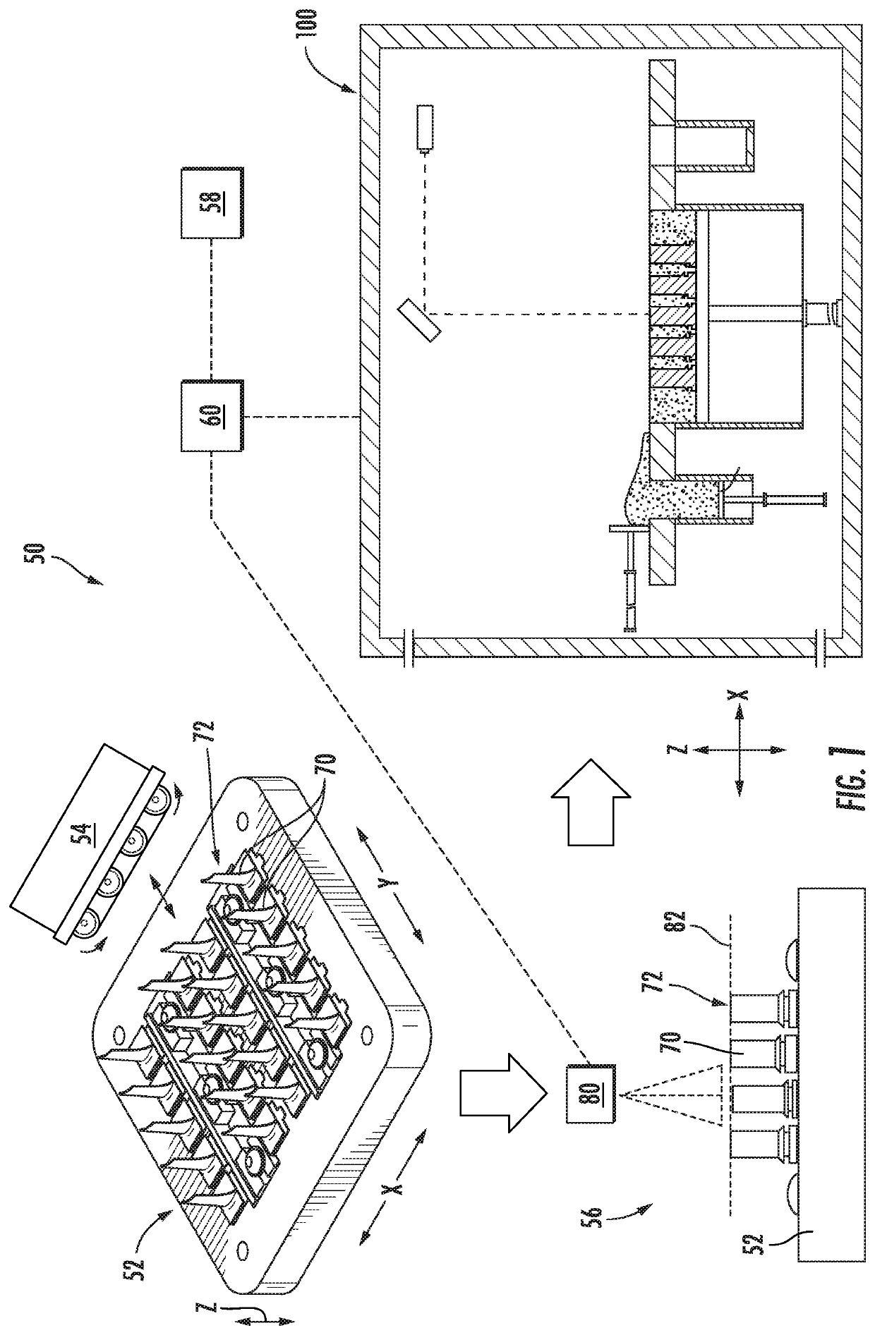
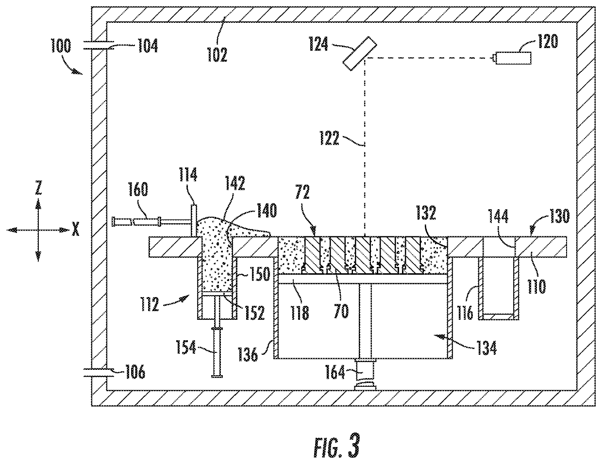
A tooling assembly for mounting a plurality of components, such as compressor blades, in a powder bed additive manufacturing machine to facilitate a repair process is provided. The tooling assembly includes component fixtures configured for receiving each of the compressor blades, a mounting plate for receiving the component fixtures, and a complementary fixture defining a plurality of voids within which the compressor blades are received when the complementary fixture is mounted to the mounting plate such that less powder is required to fill the powder bed.

Description

FIELD[0001]The present subject matter relates generally to additive manufacturing machines, and more particularly to tooling assemblies for decreasing powder usage in a powder bed additive manufacturing process.BACKGROUND[0002]Machine or device components frequently experience damage, wear, and / or degradation throughout their service life. For example, serviced compressor blades of a gas turbine engine show erosion, defects, and / or cracks after long term use. Specifically, for example, such blades are subject to significant stresses which inevitably cause blades to wear over time, particularly near the tip of the blade. For example, blade tips are susceptible to wear or damage from friction or rubbing between the blade tips and shrouds, from chemical degradation or oxidation from hot gasses, from fatigue caused by cyclic loading and unloading, from diffusion creep of crystalline lattices, etc.[0003]Notably, worn or damaged blades may result in machine failure or performance degradat...

Claims


Application Information

Patent Timeline
IPC IPC(8): B22F7/06B22F3/105B22F5/04B33Y10/00B33Y30/00B33Y50/02B23K26/34B23K26/354
CPCB22F2003/1042B33Y30/00B23K26/354B22F3/1055B33Y50/02B23K26/34B22F7/062B22F2003/1057B22F2007/068B33Y10/00B22F2003/1058B22F5/04B29C64/153B29C64/245B23P6/007B29C73/24F01D5/005F05D2230/31F05D2230/234F05D2230/22F01D25/285Y02P10/25B22F10/28B22F10/73B22F10/25B22F12/90B22F10/32B22F12/30
Inventor SUN, HONGQINGSHI, JINJIEWESSMAN, ANDREW EZEKIEL
Owner GENERAL ELECTRIC CO
Features
  • Generate Ideas
  • Intellectual Property
  • Life Sciences
  • Materials
  • Tech Scout
  • Unparalleled Data Quality
  • Higher Quality Content
  • 60% Fewer Hallucinations
Learn More