Device comprising interlocked monolithic flexible elements and corresponding additive manufacturing method

a monolithic flexible element and interlocking technology, applied in the direction of additive manufacturing processes, instruments, horology, etc., can solve the problems of complex manufacturing process, unsatisfactory symmetry of the construction, and known adverse phenomenon, so as to achieve the effect of simplifying the manufacturing process

Active Publication Date: 2020-07-30
CSEM CENT SUISSE DELECTRONIQUE & DE MICROTECHNIQUE SA RECH & DEV
View PDF1 Cites 5 Cited by
  • Summary
  • Abstract
  • Description
  • Claims
  • Application Information

AI Technical Summary

Benefits of technology

[0051]Typically, the device is manufactured on a building plate by implementation of the additive manufacturing process. Thanks to a suitable amended design, it might preferably be removed from the building pl...

Problems solved by technology

This bearing is thus complex to manufacture, regarding its number of independent components and the way they have to be assembled together, and can be bulky in some cases because of the contiguous arrangement of the blades.
Further, it requires dedicated hemi-cylinders for each pivot size and each stiffness (there are different stiffness for the same size of a pivot, with different blade thickness), in parallel with expensive production apparatuses, e.g. soldering or gluing jigs.
Further, that kind of construction is far from perfection regarding its symmetry because of the arrangement of its blades which is not symmetrical.
This lack of symmetry might lead to a known adverse phenomenon called axial centre shift.
U.S. Pat. No. 9,207,641 B2 discloses a similar pivot bearing used as ...

Method used


Image

  • Device comprising interlocked monolithic flexible elements and corresponding additive manufacturing method
  • Device comprising interlocked monolithic flexible elements and corresponding additive manufacturing method
  • Device comprising interlocked monolithic flexible elements and corresponding additive manufacturing method

Examples


Embodiment Construction

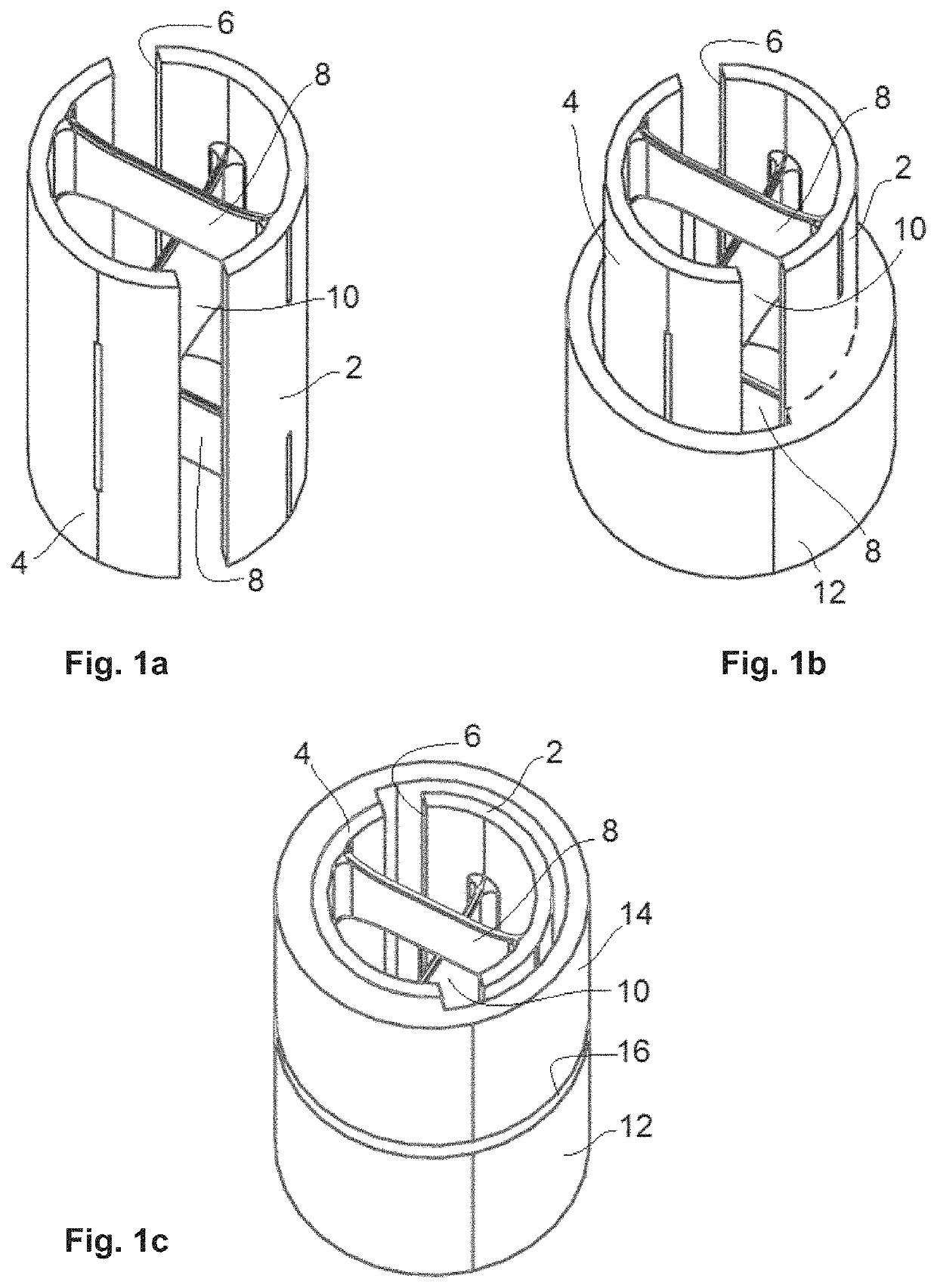
[0064]The present invention relates to the manufacture of mechanical devices, through an additive manufacturing process, which comprise a mechanical compliant mechanism comprising at least first and second flexible elements which are arranged with respect to each other so as to be interlocked, offering significant advantage over the state of the art, as explained earlier.

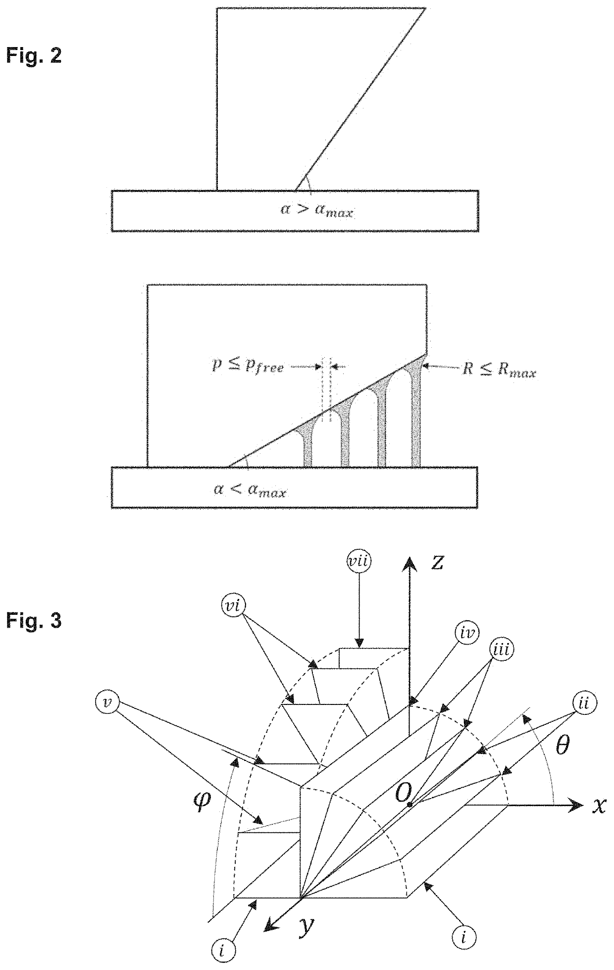
[0065]As far as the additive manufacturing process is concerned, some empirical rules have to be followed when designing a device, which can be gathered in a set of overhang rules, the process being generally taken from the group comprising Selective Laser Melting, Selective Laser Sintering, Fused Deposition Melting, Electron Beam Melting, Direct Energy Deposition, Binder Jetting and Photopolymerization. A simple non-exhaustive example of such overhang rules is schematically illustrated in FIG. 2:[0066]1) A structure tilted by less than a critical angle (αmax) with respect to the horizontal direction does require su...


PUM

PropertyMeasurementUnit
Lengthaaaaaaaaaa
Flexibilityaaaaaaaaaa
Deformation enthalpyaaaaaaaaaa

Abstract

Disclosed is a device including a compliant mechanism including: a first monolithic flexible element, having first and second ends defining a first longitudinal direction, arranged such that it is able to be subjected to an elastic deformation involving a relative movement between its first and second ends; and at least a second monolithic flexible element, having first and second ends defining a second longitudinal direction distinct from the first longitudinal direction, arranged such that it is able to be subjected to an elastic deformation involving a relative movement between its first and second ends. At least one of the first and second monolithic flexible elements includes at least one opening located between its first and second ends and defining a passage for a portion of the other monolithic flexible element such that the first and second monolithic flexible elements are interlocked.

Description

TECHNICAL FIELD[0001]The invention concerns a device comprising a compliant mechanism comprising[0002]a first monolithic flexible element, having first and second ends defining a first longitudinal direction, arranged such that it is able to be subjected to an elastic deformation involving a relative movement between its first and second ends, and[0003]at least a second monolithic flexible element, having first and second ends defining a second longitudinal direction distinct from the first longitudinal direction, arranged such that it is able to be subjected to an elastic deformation involving a relative movement between its first and second ends.[0004]A compliant mechanism is a flexible device, capable of transferring force or displacement through the elastic deformation of its mechanical structure. Very often, the flexible elements of compliant mechanisms are designed with a blade geometry, which can be generally defined as a parallelepiped with a length usually much bigger than ...

Claims


Application Information

Patent Timeline
IPC IPC(8): F16C11/12G06F30/20B29C64/245B29C64/10B29C64/393B33Y10/00B33Y30/00B33Y50/02B33Y80/00G06F113/10
CPCB29C64/393G06F30/20G06F2113/10B33Y30/00F16C11/12B29C64/245B33Y80/00B29C64/10B33Y10/00B33Y50/02F16C2220/24F16C2300/02F16C2370/00G04B17/045F16D3/74
Inventor COSANDIER, FLORENTKIENER, LIONELKRUIS, JOHANSAUDAN, HERVÉ
Owner CSEM CENT SUISSE DELECTRONIQUE & DE MICROTECHNIQUE SA RECH & DEV
Why Eureka
Try Eureka