Apparatuses and methods to strengthen mounted solar panels

Inactive Publication Date: 2020-07-30
BRIGHTSPOT AUTOMATION LLC
View PDF0 Cites 0 Cited by
  • Summary
  • Abstract
  • Description
  • Claims
  • Application Information

AI Technical Summary

Benefits of technology

[0007]The invention relates to apparatus and methods to mount solar panels in a way that the panels are supported from the rear side by spacer elements termed RailPads and RoofPads. These spacer elements press upon the rear side of the panel to displace regions of the panel away from the mounting structure. The support provided by the spacer elements reduces downward panel deflection from wind, snow, and other loads, thus minimizing tensile stress in the cells and thus minimizing solar cell crack formation and propagation. The upward bow in the panel places cells in a state of protective compressive stress. In a tensile stress state, there are forces being applied to the cells which are stretching them outward along the plane of the

Problems solved by technology

In spite of training, installation workers and Operations & Maintenance workers are also known to commonly walk on panels, and this pressure is also sufficient to crack cells.
These cracks are often closed initially after formation with minimal power loss, but over time the cracks can open up such that metallization is discontinuous across the cracks, leading to higher than desired degradation rates and risks of hot spot heating.
Should cracks occur, the trend of using a higher number of interconnect wires on each cell reduces the potential power losses.
Still other trends are adding to crack related risks such as reduced frame mass that allows module to bend more with applied loads, larger modules with center regions that are farther from the frame, thicker interconnect wires to carry the steadily increasing amounts of cell current which then cause more soldering induced microcracks in the silicon, and half-cut cells or even narrower shingled cells which have weak laser-cut edges from which cracks are more likel

Method used


Image

  • Apparatuses and methods to strengthen mounted solar panels
  • Apparatuses and methods to strengthen mounted solar panels
  • Apparatuses and methods to strengthen mounted solar panels

Examples


Embodiment Construction

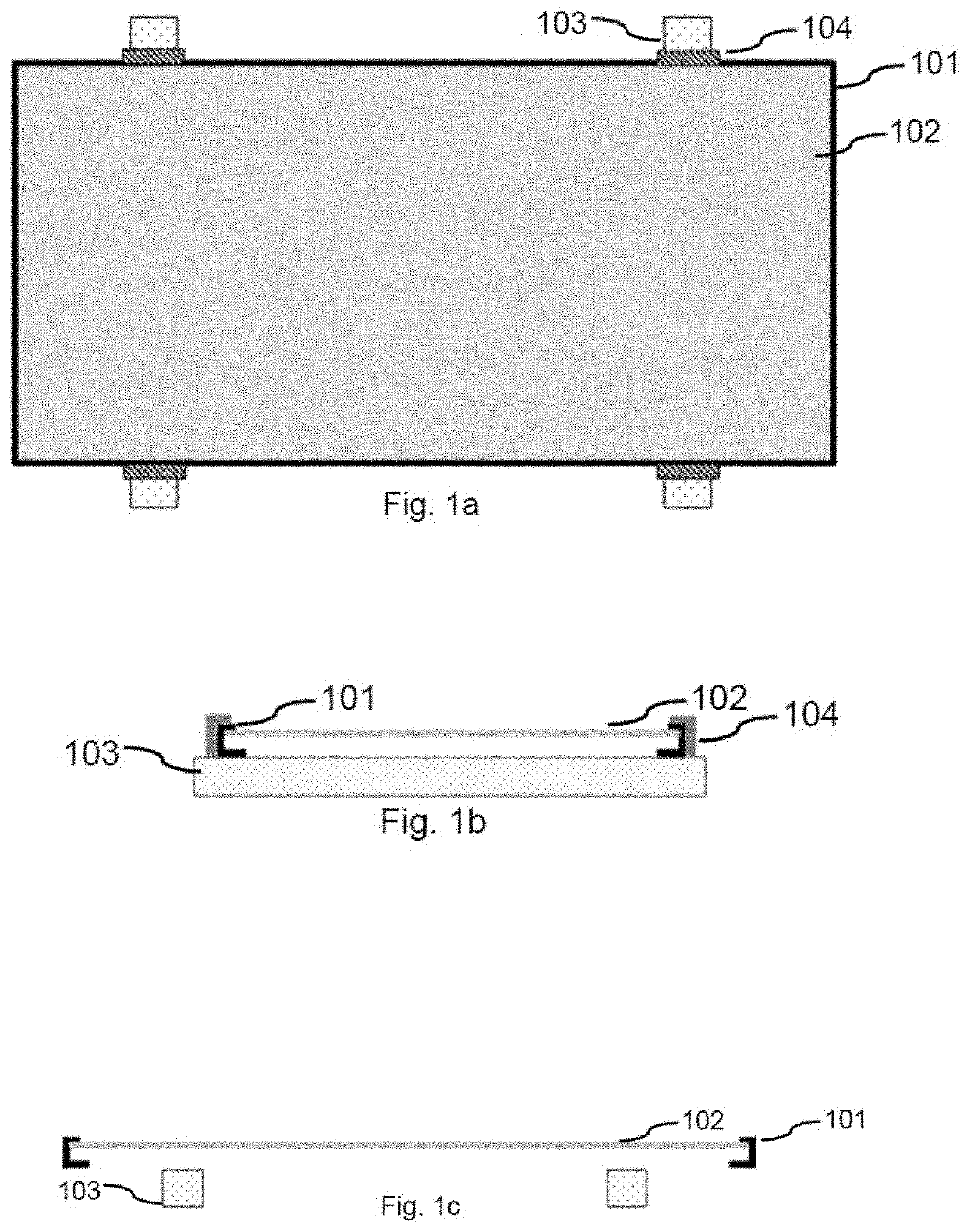
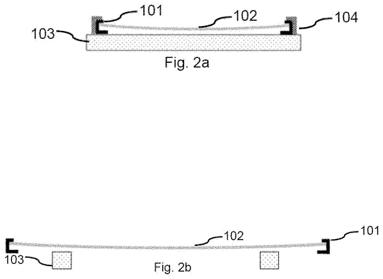
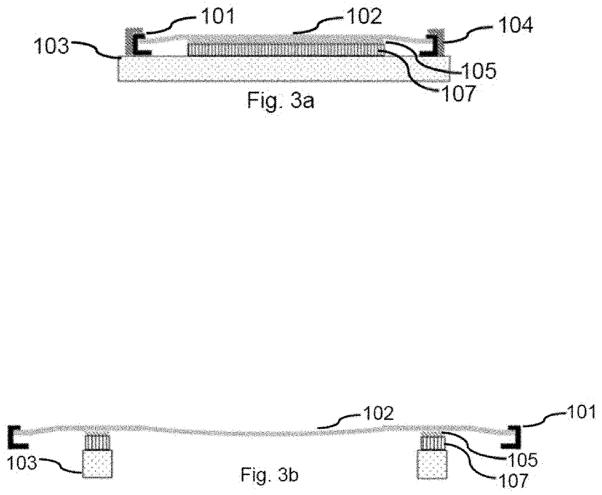
[0054]The various aspects will be described in detail with reference to the accompanying drawings. Wherever possible, the same reference numbers will be used throughout the drawings to refer to the same or like parts. References made to particular examples and implementations are for illustrative purposes, and are not intended to limit the scope of the claims.

[0055]The following detailed description is merely illustrative in nature and is not intended to limit the embodiments the application and uses of such embodiments. As used herein, the word “exemplary” means “serving as an example, instance, or illustration.” Any implementation described herein as exemplary is not necessarily preferred or advantageous over other implementations. Furthermore, there is no intention to be bound by any expressed or implied theory presented in the preceding technical field, background, brief summary or the following detailed description.

[0056]References to “one embodiment” or “an embodiment” do not ...


PUM


Abstract

Apparatus and methods to mount solar panels in a way that the panels are supported from the rear side by spacer elements termed RailPads and RoofPads are provided. These spacer elements press upon the rear side of the panel to displace regions of the panel away from the mounting structure. The support provided by the spacer elements reduces downward panel deflection from wind, snow, and other loads, thus minimizing tensile stress in the cells and thus minimizing solar cell crack formation and propagation. The upward bow in the panel places cells in a state of protective compressive stress.

Description

RELATED APPLICATIONS[0001]This application claims the benefit of priority to U.S. Provisional Patent Application No. 62 / 798,521 entitled “Method to strengthen mounted solar panels” filed Jan. 30, 2019, the entire contents of which are incorporated herein by reference.FIELD OF THE INVENTION[0002]The present invention is directed to apparatuses and methods to prevent power loss from cracked cells in solar panels.BACKGROUND OF THE INVENTION[0003]The most common solar panel design utilizing a front glass coversheet and a polymer backsheet with copper interconnect wires between silicon cells is sensitive to the tensile stress related cracking of the cells when front side mechanical loads are applied to the panel through handling, snow load, or wind load. In spite of training, installation workers and Operations & Maintenance workers are also known to commonly walk on panels, and this pressure is also sufficient to crack cells. These cracks are often closed initially after formation with ...

Claims


Application Information

Patent Timeline
IPC IPC(8): H02S20/23H02S30/10
CPCH02S20/23H02S30/10H01L31/18Y02B10/10Y02E10/50
Inventor GABOR, ANDREW M.ANSELMO, ANDREW P.JANOCH, JR., ROBERT E.
Owner BRIGHTSPOT AUTOMATION LLC
Why Eureka
Try Eureka