User defined intensity profile laser beam

a laser beam and intensity technology, applied in the field of laser materials processing, can solve the problems of overheating of the material near the edge, the speed at which objects can be printed, and the speed of throughput, so as to improve the control of the thermal profile of the part, fine resolution control

Active Publication Date: 2020-08-06
LAWRENCE LIVERMORE NAT SECURITY LLC
View PDF0 Cites 0 Cited by
  • Summary
  • Abstract
  • Description
  • Claims
  • Application Information

AI Technical Summary

Benefits of technology

[0016]All three components; gain medium (few mode or single mode), mode or phase control, and feedback together form a beam with an arbitrary intensity profile on a 3D printing surface, allowing improved control of the thermal profile of the part during printing, and allowing parallel printing over a larger area with fine resolution control.

Problems solved by technology

One general challenge in additive manufacturing is the speed at which objects can be printed, i.e., throughput.
However, when an edge is encountered, the heal in the substrate cannot propagate in all directions but is confined to a smaller volume which results in overheating the material near this edge.

Method used


Image

  • User defined intensity profile laser beam
  • User defined intensity profile laser beam
  • User defined intensity profile laser beam

Examples


Embodiment Construction

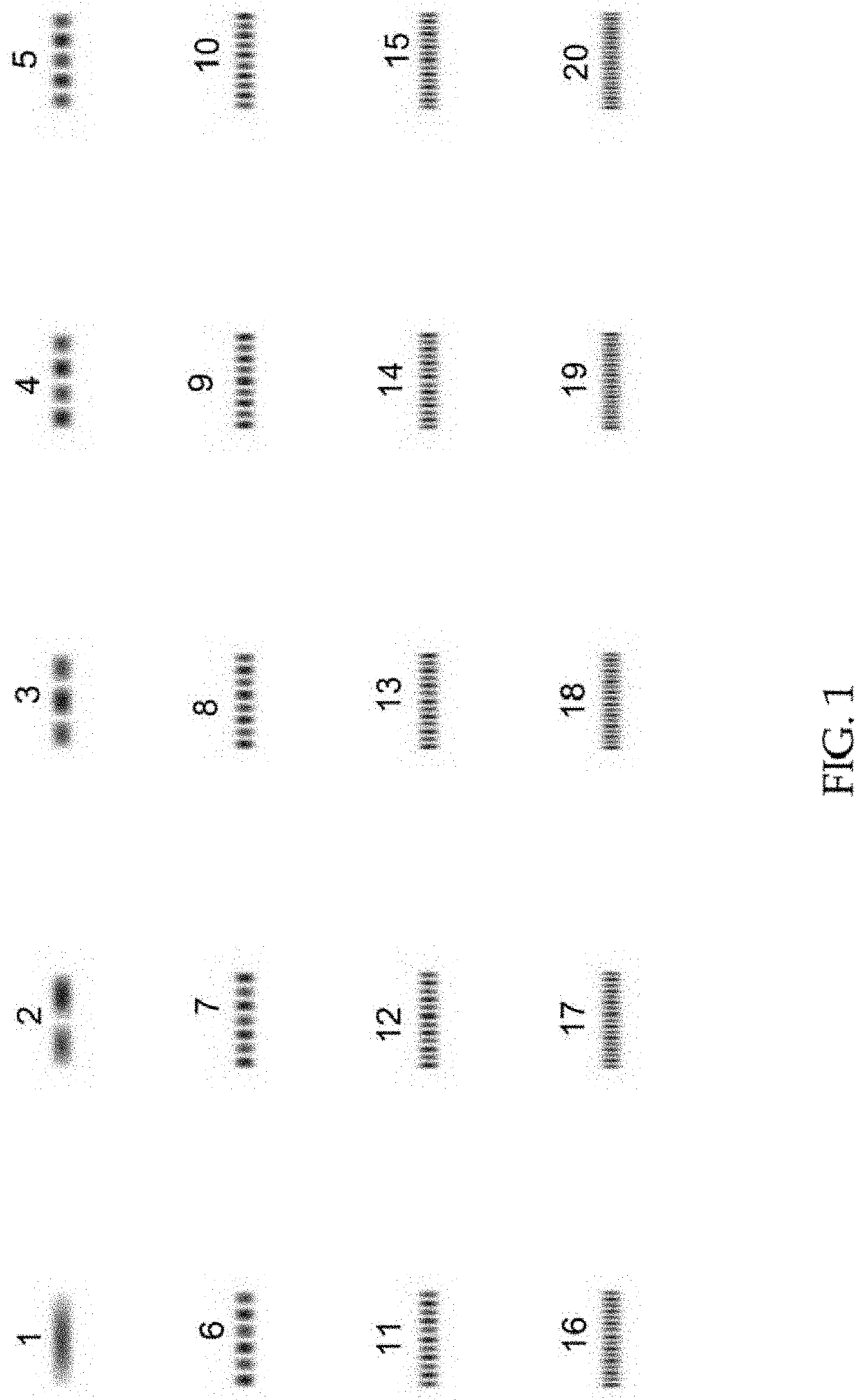
[0036]One embodiment provides the generation of arbitrary intensity profiles by multi-mode interference in a multi-mode ribbon fiber. The concept here is to generate an intensity profile with a line of regularly spaced hot-spots, or lobes, each of which can be arbitrarily turned “on” or “off”; that is, pixels. This can be accomplished by judiciously arranging interference amongst the modes of a slab waveguide. Starting with the slab mode with the desired number of lobes, the relative intensity of each lobe can be adjusted by including some portion of the other modes, with appropriate amplitude and phase, such that the coherent summation of fields yields the desired profile. Mote that in this scheme, the required number of control channels is equal to (at most) the number of modes supported by the waveguide.

[0037]Selection of the required mode complex amplitudes can be done by mode filtering external to the fiber (slab) amplifier; or by seeding the amplifier with a low power pattern ...


PUM

PropertyMeasurementUnit
dimensionaaaaaaaaaa
poweraaaaaaaaaa
surface roughnessaaaaaaaaaa

Abstract

A high-power laser beam with an arbitrary intensity profile is produced. Such beam has a variety of uses including for laser materials processing such as powder bed fusion additive manufacturing. Several challenges in additive manufacturing are mitigated with the present non-uniform intensity laser profiles. Nonuniform shapes include a set of intensity pixels in a line that could print a wide stripe area instead of just a single line. One example uses the multimode interference pattern from the output of a ribbon fiber which is imaged onto a work piece. The interference pattern is controlled to allow turning on or off of ‘pixels’ along a line which can be used to shape the beam and form the additively manufactured part.

Description

Statement Regarding Federally Sponsored Research or Development[0001]The United States Government has rights in this invention pursuant to Contract No. DE-AC52-07NA27344 between the U.S. Department of Energy and Lawrence Livermore National Security, LLC, for the operation of Lawrence Livermore National Laboratory.BACKGROUND OF THE INVENTIONField of the Invention[0002]The present invention relates to laser materials processing, anti more specifically, it relates to techniques for producing a desired intensity profile laser beam for use in laser-based additive manufacturing.Description of Related Art[0003]The recent growth of additive manufacturing technology—also known as 3D printing—and use in industry and government has spurred interest at Lawrence Livermore National laboratory (LLNL) in improved lasers and techniques for laser-based printing. Laser based additive manufacturing has been accomplished by the use of a single Gaussian beam incident on the printing surface. The power of...

Claims


Application Information

Patent Timeline
Patent Type & Authority Applications(United States)
IPC IPC(8): H01S3/067H01S3/00H01S3/10
CPCH01S3/10015H01S3/06729H01S3/10053H01S3/0085B23K26/073B33Y30/00B29C64/268G02B1/005G02B6/02042G02B6/262G02B26/103H01S3/005H01S2301/20B23K26/0617H01S3/1003H01S3/10038H01S3/2308H01S3/1001
Inventor DRACHENBERG, DERREK R.DAWSON, JAY W.GUSS, GABRIEL M.PAX, PAUL H.RUBENCHIK, ALEXANDER M.MATTHEWS, MANYILIBO J.
Owner LAWRENCE LIVERMORE NAT SECURITY LLC
Why Eureka
Try Eureka