Supercharge Your Innovation With Domain-Expert AI Agents!

Lighter-weight casing made of composite material and method of manufacturing same

a composite material and light-weight technology, applied in the field of gas turbine casings, can solve the problems of limited extent to which fiber reinforcement can be made thicker in the retention zone, and achieve the effect of improving the strength of the fiber reinforcemen

Active Publication Date: 2020-08-27
SN DETUDE & DE CONSTR DE MOTEURS DAVIATION S N E C M A +1
View PDF0 Cites 0 Cited by
  • Summary
  • Abstract
  • Description
  • Claims
  • Application Information

AI Technical Summary

Benefits of technology

The patent describes a method for making a casing for a gas turbine engine. The method involves adding a textile layer between the layers of fiber texture used for reinforcing the casing. This textile layer can be adjusted to create a thicker portion of the casing without changing the overall warp-weft ratio. This thicker portion can serve as a retention shield or zone to prevent debris or objects from entering the engine. The method also allows for a thicker retention zone while minimizing the overall weight of the casing. The text describes the use of different types of fibers and weaving techniques to ensure better cohesion and uniform force transmission between the fiber texture layers and the textile strip layers. The technical effects of this method include improved retention of debris, reduced weight of the casing, and better mechanical behavior between the fiber texture layers and the textile strip layers.

Problems solved by technology

Nevertheless, with that fabrication technique, the extent to which the fiber reinforcement can be made thicker in the retention zone is limited firstly by the weavability of a texture having strands of diameter that is too great (or too small) (weavability limit for 3D woven fabrics), and secondly by the maximum acceptable warp-weft ratio (WWR).

Method used


Image

  • Lighter-weight casing made of composite material and method of manufacturing same
  • Lighter-weight casing made of composite material and method of manufacturing same
  • Lighter-weight casing made of composite material and method of manufacturing same

Examples


Embodiment Construction

[0046]The invention is described below in the context of its application to a gas turbine aeroengine fan casing.

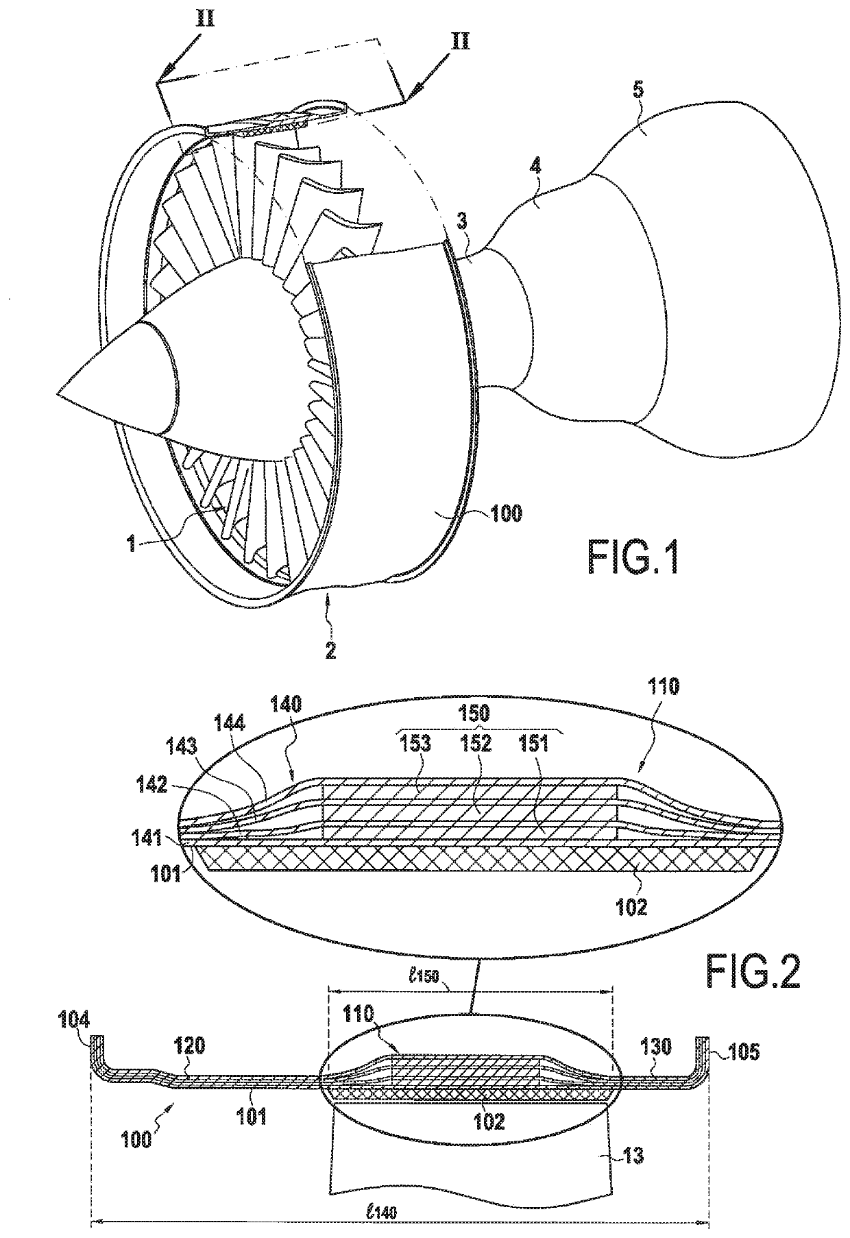
[0047]Such an engine, as shown very diagrammatically in FIG. 1, comprises going from upstream to downstream in the flow direction of the gas stream: a fan 1 arranged at the inlet of the engine; a compressor 2; a combustion chamber 3; a high pressure turbine 4; and a low pressure turbine 5.

[0048]The engine is housed inside a casing comprising a plurality of portions corresponding to different elements of the engine. Thus, the fan 1 is surrounded by a fan casing 100.

[0049]FIG. 2 is a profile view of the composite material fan casing 100 that can be obtained by a method of the invention. The inner surface 101 of the casing defines the air inlet passage. It may be provided with a layer of abradable material 102 in register with the path followed by the tips of the fan blades, one blade 13 being shown in part and in highly diagrammatic manner. The abradable coating is thus rang...


PUM

PropertyMeasurementUnit
Weightaaaaaaaaaa
Thicknessaaaaaaaaaa
Ratioaaaaaaaaaa

Abstract

A method of fabricating a composite material casing of varying thickness for a gas turbine includes using three-dimensional or multilayer weaving to make a fiber texture in the form of a strip; winding the fiber texture as a plurality of superposed layers onto a mandrel of profile corresponding to the profile of the casing to be fabricated, so as to obtain a fiber preform of shape corresponding to the shape of the casing to be fabricated; and densifying the fiber preform with a matrix. During winding of the fiber texture on the mandrel, a textile strip is interposed between the adjacent turns of the fiber texture, the textile strip presenting a width that is less than the width of the fiber texture and defining a retention zone of the casing.

Description

BACKGROUND OF THE INVENTION[0001]The invention relates to gas turbine casings, and more particularly but not exclusively to gas turbine fan casings for aeroengines.[0002]In a gas turbine aeroengine, the fan casing performs several functions. It defines the air inlet passage into the engine, it supports an abradable material facing the tips of the fan blades, it supports an optional soundwave absorber structure for acoustic treatment at the inlet to the engine, and it incorporates or supports a retention shield. The retention shield constitutes a debris trap for retaining debris such as ingested objects or fragments of damaged blades that are projected by centrifuging, in order to prevent them from passing though the casing and reaching other portions of the aircraft.[0003]Casings, such as fan casings, used to be made of metal material, but they are now made out of composite material, i.e. from a fiber preform that is densified by an organic matrix, which makes it possible to fabrica...

Claims


Application Information

Patent Timeline
IPC IPC(8): F01D25/24B29C70/24B29C70/32B32B3/12B32B5/02B32B5/18B32B5/24B32B5/26B32B27/12B29C70/48
CPCB32B2605/18B29C70/24B29C70/48F05D2300/60B32B5/245B32B5/024B32B2260/023B32B2260/046F01D25/24B32B27/12B29C70/32B32B3/12B32B5/26B32B2250/44B32B2255/02B32B5/18B29C70/88F01D21/045B32B15/14B32B15/20B32B27/34B32B1/00B32B2262/0269B32B2262/101B32B2262/105B32B2262/106B32B2266/0242B32B2266/08B32B2307/50B32B2307/732B32B2571/00Y02T50/60B29B11/16
Inventor FABRE, HUBERT JEAN-MARIEHELLOT, JÉRÉMYPHELIPPEAU, ANTOINEMARCHAL, YANN DIDIER SIMONDAMBRINE, BRUNO JACQUES GÉRARD
Owner SN DETUDE & DE CONSTR DE MOTEURS DAVIATION S N E C M A
Features
  • R&D
  • Intellectual Property
  • Life Sciences
  • Materials
  • Tech Scout
  • Unparalleled Data Quality
  • Higher Quality Content
  • 60% Fewer Hallucinations
Learn More