Catheter with Seal Layer

a seal layer and catheter technology, applied in the field of medical devices, can solve the problems of difficult access to the transducer assembly, difficulty in placing by medical professionals, and difficulty in ensuring the safety of the patient, so as to improve the visibility of the distal end

Inactive Publication Date: 2020-09-24
AVENT INC
View PDF0 Cites 4 Cited by
  • Summary
  • Abstract
  • Description
  • Claims
  • Application Information

AI Technical Summary

Benefits of technology

[0021]In yet another embodiment, the transducer can transmit and receive signals for detection by an ultrasound imaging system, wherein the transducer enhances the visibility of the distal end of the catheter on an ultrasound image.

Problems solved by technology

One problem during procedures that utilize ultrasound imaging, such as regional anesthesia nerve block procedures or biopsy procedures, is the accurate placement of a needle in order to deliver the nerve block (e.g., via the delivery of an anesthetic through the needle, via the insertion of a catheter to deliver the nerve block via RF energy, or via the combination of the delivery of an anesthetic and RF energy) to the desired nerve bundle or to biopsy the correct tissue sample.
Therefore, as the needle, when used, is generally removed after placement of the catheter, it can be difficult for medical professionals to easily place, or confirm the continued placement of the catheter after removal of the needle containing the transducer.
While minimizing the signal noise is important, the size of the typical coaxial cable required to sufficiently minimize the signal noise can be problematic when it is desired to advance the transducer assembly to a nerve bundle or tissue or to remain connected to a patient for a period of time.
For instance, the increased diameter of the transducer assembly due to the presence of a large coaxial cable can make it difficult for the transducer assembly to reach a target nerve bundle or tissue located beneath several layers of skin, muscle, etc, and also becomes problematic as the large size may increase the likelihood of contact or pulling by the patient, increasing the changes of movement from the target.

Method used


Image

  • Catheter with Seal Layer
  • Catheter with Seal Layer
  • Catheter with Seal Layer

Examples


Embodiment Construction

[0037]Reference will now be made in detail to embodiments of the present invention, examples of which are illustrated in the figures. Each embodiment is provided by way of explanation of the invention and is not meant as a limitation of the invention. For example, features illustrated or described as part of one embodiment may be used with another embodiment to yield still a further embodiment. It is intended that the present invention include these and other modifications and variations coming within the scope and spirit of the invention.

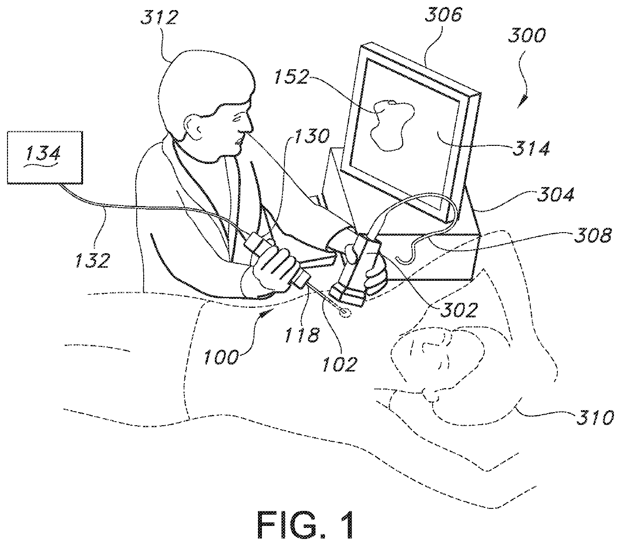
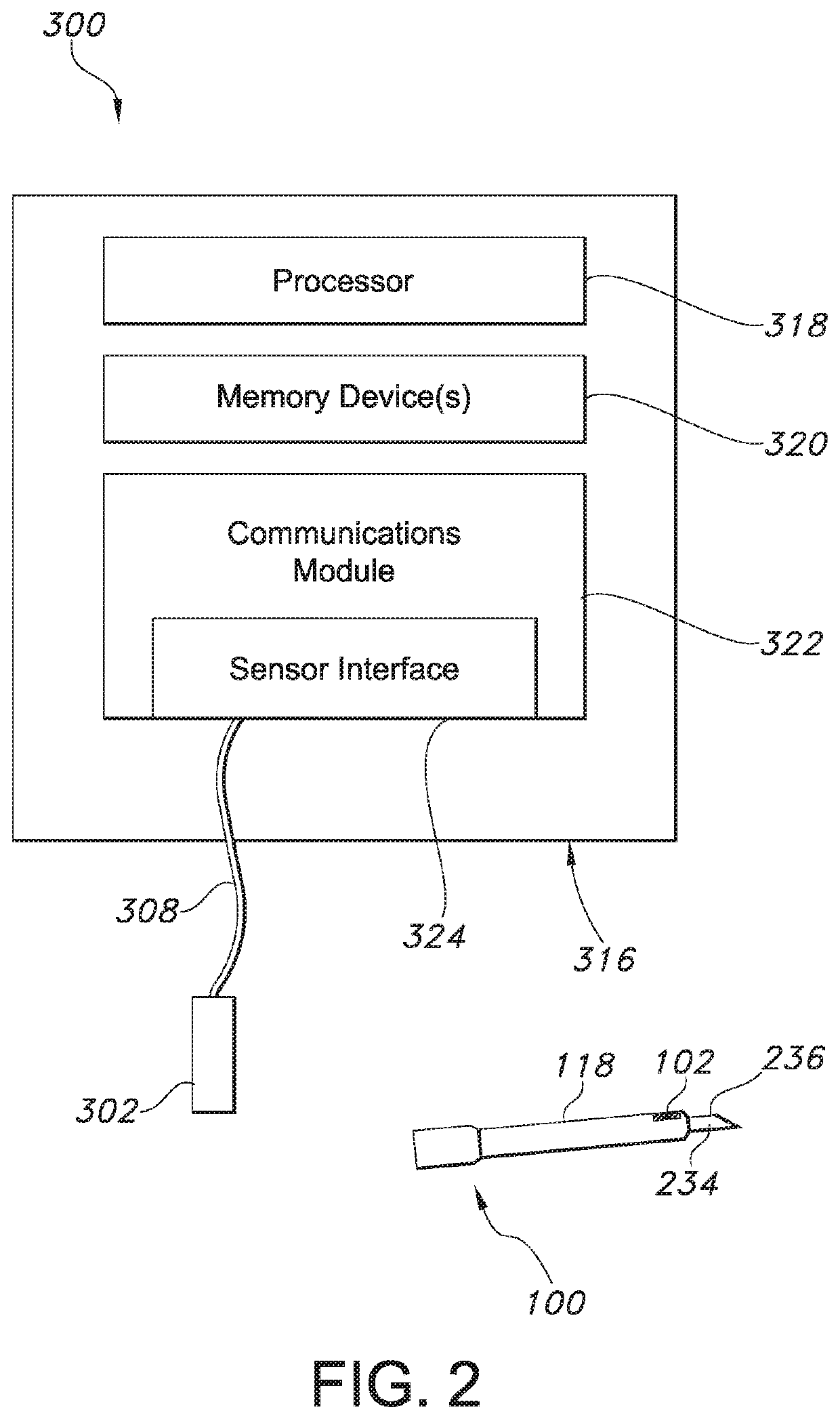
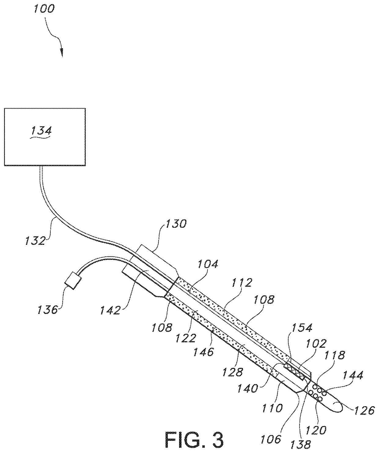
[0038]Generally speaking, the present invention is directed to a catheter assembly for locating an object of interest (e.g., an anatomical region such as a muscle, nerve bundle, etc.) or maintaining and / or confirming that the catheter assembly remains at an object of interest for a period of time. For instance, the catheter assembly may generally include a transducer. Thus, the catheter assembly may be initially located at an object of interest, an...


PUM


Abstract

A catheter assembly for locating an object of interest (e.g., an anatomical region such as a muscle, nerve bundle, etc.) is provided. The catheter assembly includes a catheter having a catheter body defining a proximal end and a distal end; a transducer located at the distal end of the catheter; one or more transducer wires extending from a proximal end of the transducer towards the proximal end of the catheter; and a length of tubing surrounding the catheter, the transducer, and the one or more transducer wires, wherein the length of tubing has a proximal portion and a distal portion, wherein the proximal portion surrounds the one or more transducer wires and the distal portion surrounds the transducer, wherein the proximal portion includes a conductive filler.

Description

FIELD OF THE INVENTION[0001]The present invention relates generally to medical devices used in conjunction with ultrasound imaging systems, and more particularly to devices used in medical procedures such as nerve blocks, biopsies, or any other procedure where access is provided via a catheter.BACKGROUND OF THE INVENTION[0002]Detection of anatomical objects using medical imaging is an essential step for many medical procedures, such as regional anesthesia nerve blocks, and is becoming the standard in clinical practice to support diagnosis, patient stratification, therapy planning, intervention, and / or follow-up. Various systems based on traditional approaches exist for anatomical detection and tracking during medical procedures, such as computed tomography (CT), magnetic resonance (MR), ultrasound, and fluoroscopic imaging systems.[0003]For example, ultrasound imaging systems utilize sound waves with frequencies higher than the upper audible limit of human hearing. Further, ultrasou...

Claims


Application Information

Patent Timeline
Patent Type & Authority Applications(United States)
IPC IPC(8): A61B8/12A61B5/00A61B8/00
CPCA61B8/4245A61B2090/378A61B5/0084A61B8/445A61B8/12A61B8/4461A61B8/4483A61B8/0841A61B8/56A61B17/3478A61B2090/3782A61B2090/3784A61B2090/3925
Inventor KHALAJ, STEVE S.SHAHRIARI, SHIRZAD
Owner AVENT INC
Why Eureka
Try Eureka