Magneto-optic kerr effect metrology systems

Active Publication Date: 2020-09-24
KLA TENCOR CORP
View PDF0 Cites 4 Cited by
  • Summary
  • Abstract
  • Description
  • Claims
  • Application Information

AI Technical Summary

Benefits of technology

The patent text describes a system for directing a laser beam onto a wafer for metrology purposes. The laser beam is transformed from a Gaussian beam profile to a hollowed laser ring using an axicon telescope, which is either a transmissive or reflective telescope. The transformed laser beam is then directed onto the wafer either through a beam splitter or fold mirror. A detector receives the reflected laser beam from the wafer. The system includes a focal lens and a magneto-optic Kerr effect metrology system. The invention allows for improved accuracy in measuring the characteristics of the laser beam and the wafer.

Problems solved by technology

Exact fit to the data is typically impossible and some criterion may be needed to define, especially for measurements on thin (<10 nm) films where sensitivity is low.
Most laser scanners use moveable mirrors to steer the laser beam, but this method may be unable to achieve accurate laser position and repeatability because of the mechanical tolerance.
However, this technique has the disadvantage of low efficiency.
More than half of the laser power cannot be used in the output due to the diffractive efficiency.
The laser power loss using this technique was large.
The acquisition speed was limited by the detector arrays and this technique could not be used with a sampling rate larger than 10 kHz.
This technique had unacceptable laser / light power loss.

Method used


Image

  • Magneto-optic kerr effect metrology systems
  • Magneto-optic kerr effect metrology systems
  • Magneto-optic kerr effect metrology systems

Examples


Embodiment Construction

lass="d_n">[0041]Although claimed subject matter will be described in terms of certain embodiments, other embodiments, including embodiments that do not provide all of the benefits and features set forth herein, are also within the scope of this disclosure. Various structural, logical, process step, and electronic changes may be made without departing from the scope of the disclosure. Accordingly, the scope of the disclosure is defined only by reference to the appended claims.

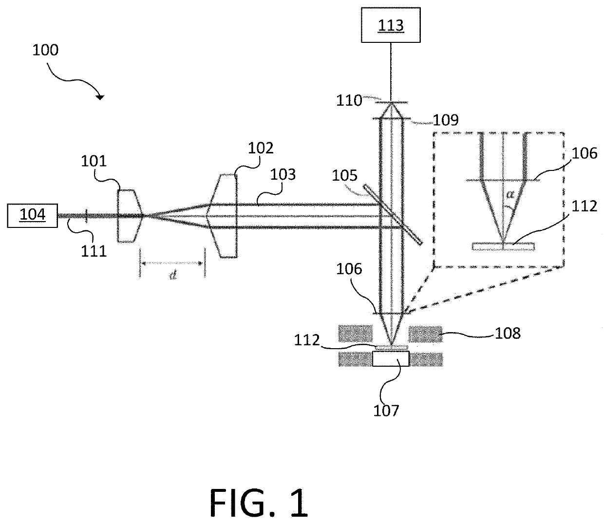
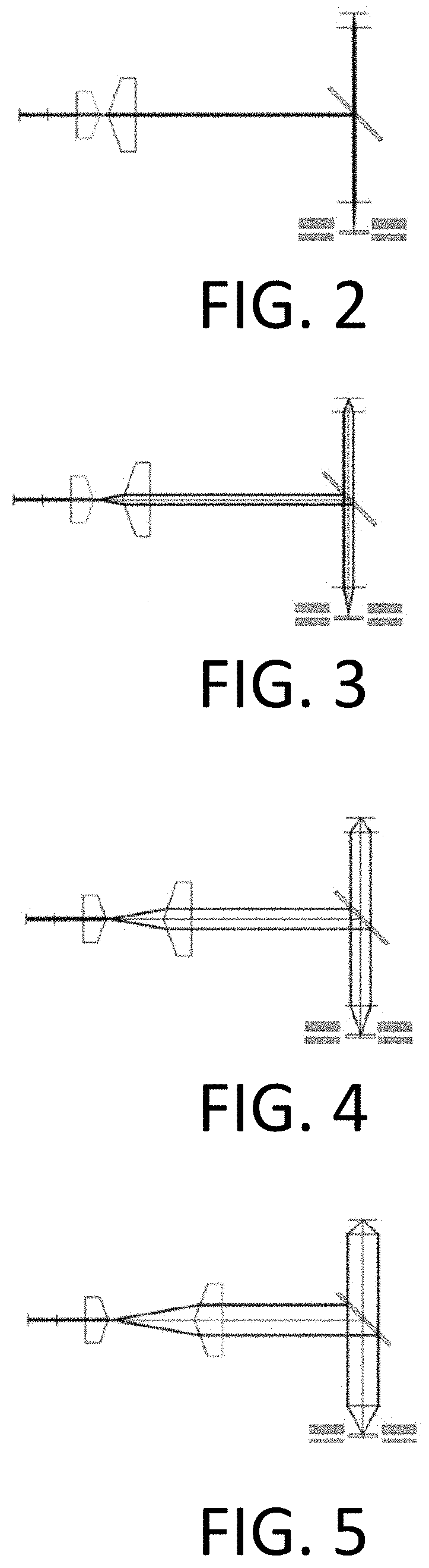
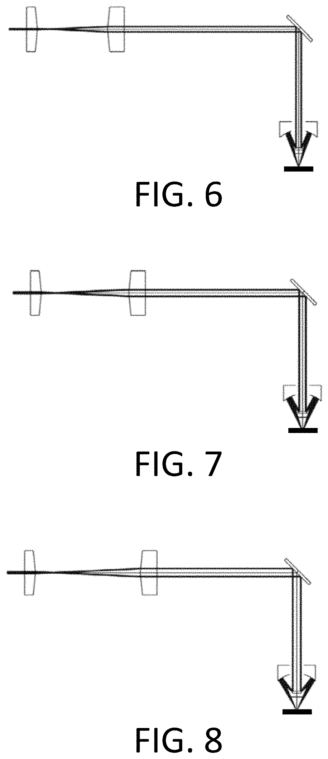
[0042]Optical systems that provide variable incident angle with high spatial resolution in a magneto-optic Kerr effect (MOKE) metrology system are disclosed. The embodiments disclosed herein have the can continuously change the laser incident angle in a large scale and focus the laser beam into a small size, which can provide an easier and broader way to detect the MOKE signal of a patterned wafer. For example, the embodiments disclosed herein can be used to detect a MOKE signal of memory chips, such as on the ...


PUM


Abstract

A laser beam is directed through a transmissive axicon telescope or a reflective axicon telescope such as in a magneto-optic Kerr effect metrology system. With the transmissive axicon telescope, a Gaussian beam profile is directed through a first axicon lens and a second axicon lens. The first axicon lens and second axicon lens transfer the Gaussian beam profile of the laser beam to a hollowed laser ring. The laser beam with a hollowed laser ring can be directed through a Schwarzschild reflective objective. With the reflective axicon telescope, the laser beam is directed through two conical mirrors that are fully reflective. One of the conical mirrors defines a central hole that the laser beam passes through.

Description

CROSS-REFERENCE TO RELATED APPLICATIONS[0001]This application claims priority to the provisional patent application filed Mar. 20, 2019 and assigned U.S. App. No. 62 / 821,098, the provisional patent application filed Apr. 6, 2019 and assigned U.S. App. No. 62 / 830,372, and the provisional patent application filed Apr. 22, 2019 and assigned U.S. App. No. 62 / 836,821, the disclosures of which are hereby incorporated by reference.FIELD OF THE DISCLOSURE[0002]This disclosure relates to metrology systems for semiconductor wafers.BACKGROUND OF THE DISCLOSURE[0003]Evolution of the semiconductor manufacturing industry is placing greater demands on yield management and, in particular, on metrology and inspection systems. Semiconductor device critical dimensions (CD) continue to shrink, profiles become more complex, and vertical dimensions continue to increase, yet the industry needs to decrease time for achieving high-yield, high-value production. Improved measurement sensitivity is needed. Min...

Claims


Application Information

Patent Timeline
IPC IPC(8): G11B11/105
CPCG11B11/10506H01L22/12G02B5/001G01R33/0325G02B23/02G02B17/06G01B11/06G01B11/24H01S3/0014G11B11/10521G11B11/1051
Inventor WANG, JUNZHENG, YAOLEILI, CHUNXIAYAN, CHANGFEIDONG, LANSHENGZHOU, YANGYOU, HAI-YANGPENG, HAIJINGSHI, JIANOUNI, RUIKRISHNAN, SHANKARWANG, DAVID Y.JOHNSON, WALTER H.BLASENHEIM, BARRY
Owner KLA TENCOR CORP
Why Eureka
Try Eureka