
Honeycomb filter

a filter and honeycomb technology, applied in the field of honeycomb filters, can solve the problems of easy falling off of the end of the plugging portion, damage to the plugging portion, and difficult to obtain satisfactory achieve the effects of improving exhaust gas purification performance, high isostatic strength, and effective restrainting the plugging portion from falling o

Active Publication Date: 2020-10-01
NGK INSULATORS LTD
View PDF0 Cites 2 Cited by
  • Summary
  • Abstract
  • Description
  • Claims
  • Application Information

AI Technical Summary

Benefits of technology

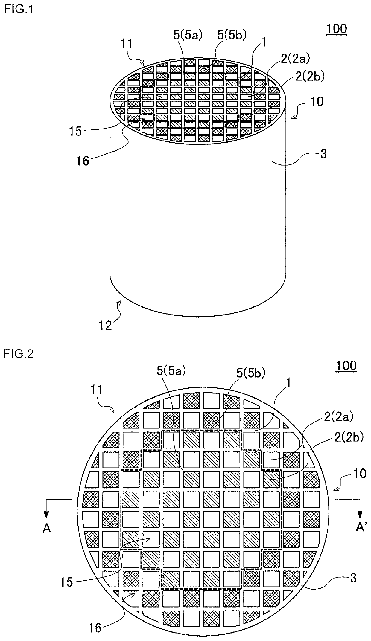
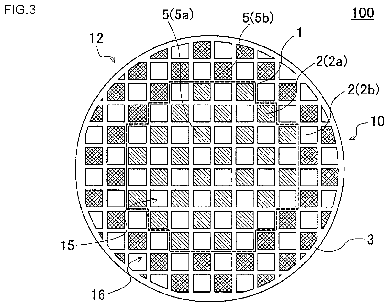
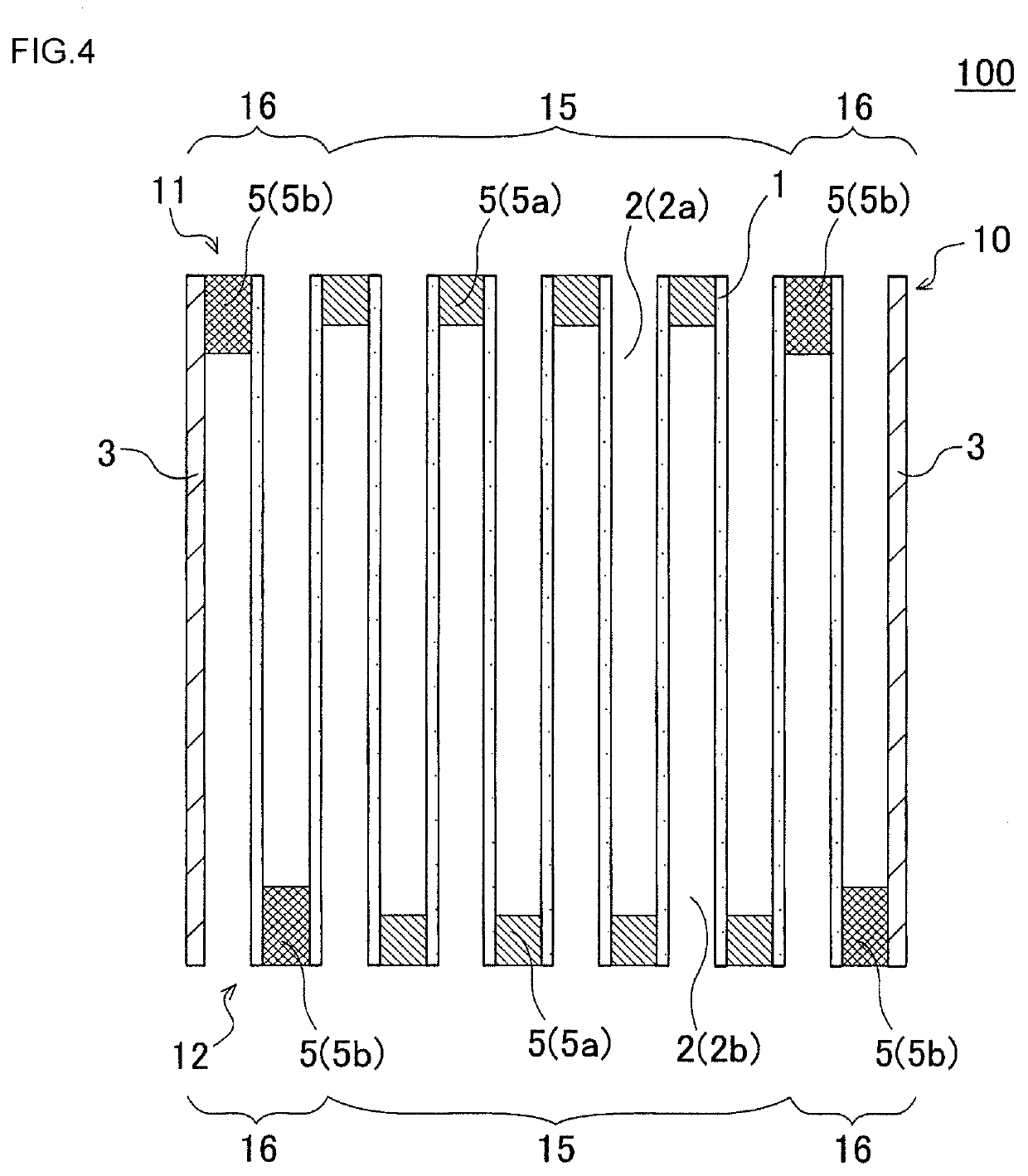
The present invention provides a honeycomb filter that can improve exhaust gas purification performance, prevent plugging portions from falling off, and have high isostatic strength. The honeycomb filter has a honeycomb structure with higher porosity, and the plugging length of the central and circumferential plugging portions is designed to optimize the mass and temperature rise properties of the honeycomb filter, allowing for quick activation of the exhaust gas purifying catalyst. The relatively larger plugging length of the circumferential plugging portions also improves its isostatic strength, effectively suppressing damage to the honeycomb filter during canning under high compression surface pressure. Additionally, the design of the honeycomb filter reduces the possibility of the holding material edge being positioned near the boundary between the plugging portions and void portions of the cells, resulting in improved retention of the plugging portions.

Problems solved by technology

Conventional honeycomb filters have been posing a problem in that, when the honeycomb filters are loaded with an exhaust gas purifying catalyst, it is difficult to obtain satisfactory exhaust gas purification performance.
Further, conventional honeycomb filters pose a problem in that plugging portions easily fall off from the ends of cells.
There has been another problem in that the plugging portions are damaged due to various types of stresses applied to the honeycomb filters even if the plugged portions do not fall off.
Even when such canning is performed, plugging portions fall off from the ends of cells or the plugging portions are damaged in some cases.
In such a case, sometimes, in the cells positioned on the circumferential side of the honeycomb filter, the edge of the holding material is inconveniently positioned at the boundary between the plugging portions and the void portions of the cells, causing the plugging portions to easily fall off due to a high stress applied to the vicinity of the above boundary from the holding material.
For example, at the time of canning a honeycomb filter, the honeycomb filter is damaged by a compression surface pressure in some cases.

Method used


Image

  • Honeycomb filter
  • Honeycomb filter
  • Honeycomb filter

Examples


example 1

[0070]Ten parts by mass of a pore former, 20 parts by mass of a dispersing medium, and 1 part by mass of an organic binder were added to 100 parts by mass of a cordierite forming raw material and mixed, and the mixture was kneaded to prepare a kneaded material. As the cordierite forming raw material, alumina, aluminum hydroxide, kaolin, talc, and silica were used. As the dispersing medium, water was used. As the organic binder, methylcellulose was used. As a dispersing agent, dextrin was used. As the pore former, coke having an average particle diameter of 15 μm was used.

[0071]Subsequently, the kneaded material was subjected to extrusion using a die for making honeycomb formed bodies thereby to obtain a honeycomb formed body, the entire shape of which was a round pillar shape. The shape of the cells of the honeycomb formed body was quadrangular.

[0072]Subsequently, the honeycomb formed body was dried by a microwave drier, and further dried by a hot air drier to completely dry the hon...

examples 2 to 6

[0095]Honeycomb filters were made according to the same method as that used for the honeycomb filter of Example 1 except that the configurations of the honeycomb filters were changed as shown in Table 1.


PUM

PropertyMeasurementUnit
plugging length L2aaaaaaaaaa
porosityaaaaaaaaaa

Abstract

A honeycomb filter includes a pillar-shaped honeycomb structure having porous partition walls provided, surrounding a plurality of cells which serve as fluid through channels extending from an inflow end face to an outflow end face, and porous plugging portions provided either at the ends on the inflow end face or the outflow end face of the cells, wherein the plugging portions are composed of a porous material, the honeycomb structure has a central region and a circumferential region and a ratio of an area of the circumferential region with respect to that of the central region ranges from 0.1 to 0.5, and a plugging length L1 in the cell extending direction of a central plugging portion in the central region is smaller than a plugging length L2 of a circumferential plugging portion in the circumferential region, L1 ranges from 3 to 6 mm, and L2 from 7 to 9 mm.

Description

[0001]The present application is an application based on JP 2019-066134 filed on Mar. 29, 2019 with Japan Patent Office, the entire contents of which are incorporated herein by reference.BACKGROUND OF THE INVENTIONField of the Invention[0002]The present invention relates to a honeycomb filter. More particularly, the present invention relates to a honeycomb filter which, when loaded with an exhaust gas purifying catalyst, enables exhaust gas purification performance to be improved, effectively restrains plugging portions from falling off from cells, and exhibits high isostatic strength.Description of the Related Art[0003]Hitherto, as a filter adapted to trap particulate matter in an exhaust gas emitted from an internal combustion engine, such as a diesel engine, or a device adapted to purify toxic gas components, such as CO, HC, and NOx, there has been known a honeycomb filter using a honeycomb structure (refer to Patent Documents 1 to 4). The honeycomb structure has partition walls ...

Claims


Application Information

Patent Timeline
Patent Type & Authority Applications(United States)
IPC IPC(8): B01J35/04C04B38/00
CPCC04B38/0009B01J35/04B01D2255/9202B01D53/885B01D2255/9205F01N3/0222F01N3/035F01N3/2828F01N2330/34F01N2330/48C04B38/0012C04B2111/00793C04B2111/0081B01D2255/9155B01J35/56C04B35/00
Inventor YOSHIOKA, FUMIHIKO
Owner NGK INSULATORS LTD
Learn More