Additive manufacturing device, additive manufacturing method, and profile rod therefor

a technology of additive manufacturing and profile rod, which is applied in the field of additive manufacturing device and additive manufacturing method, and the field of profile rod therefor, can solve the problems of in-situ impregnation, significantly more complex in terms of the quality of the part, and inability to achieve the effect of reducing the complexity of the additive manufacturing device, and improving the layered melting

Active Publication Date: 2020-10-01
AIRBUS OPERATIONS GMBH
View PDF0 Cites 4 Cited by
  • Summary
  • Abstract
  • Description
  • Claims
  • Application Information

AI Technical Summary

Benefits of technology

[0080]Advantageous effects of the invention will be explained in more detail hereunder. It is to be noted that not all of the advantages have to be implemented in each embodiment. Advantages can also be implemented to varying degrees in different embodiments.
[0081]The basic concept of the invention is to eliminate the limitations which can result from the use of filament coils, in particular for fiber-reinforced filaments, and to overall improve the layered melting in particular with a view to the deposition rate such that a production of components at an industrial scale is reasonably possible.
[0082]To this end, it is proposed that pre-cut, pre-impregnated and reinforced fiber profile rods are used. For example, in the form of a square rod or a round rod, or else other suitable cross-sectional shapes. The typical diameter of the profile rods can be between approximately 2 mm and 20 mm, in particular between 5 mm and 15 mm. In principle however, the diameter of the profile rods is ly limited by the manageability thereof.
[0083]The pre-cutting of the bars enables the cutting unit to be removed from the printing head and thus to reduce the complexity of the additive manufacturing device such that also less maintenance is required during the printing process.
[0084]On account of the profile rods having a limited profile rod length, an almost arbitrary cut length can be used up to the point at which the handling of the profile rods becomes excessively difficult while endless fibers can still be used. Fibers which have a length that is identical to the dimensions of the component are preferably referred to as “endless” herein. In other words, when the fibers in one layer extend along the entire length of the layer, the fibers are presently referred to as endless.
[0085]The use of pre-impregnated materials, so-called prepregs, in a profile rod shape (for example thermoplastic unidirectional fiber-reinforced profiles, “UD profiles”) enables the use of high-quality semi-finished products having a comparatively large diameter, while the low deposition rates which arise in the case of semi-finished products having a small diameter, such as with filament coils, for instance, can be avoided.

Problems solved by technology

This enables the use of comparatively long filaments but is associated with certain limitations in terms of the filaments used.
One limitation can thus be that the filaments used have a rather small diameter (usually between 0.8 mm and less than 3 mm), so as to permit the winding and guiding by way of acceptable bending radii.
Alternative methods such as, for example, the use of yarns mixed in, or an in-situ impregnation, can be significantly more complex in terms of the part quality that can be obtained, in particular by virtue of the additional complexity of the method.
While cutting devices of this type exist, this approach may be less desirable because the cutting of the fibers may be a limitation in terms of the continuous operation of the 3D printer.
In another case, the accumulation of degraded thermoplastic material at the exit of the printing nozzle can represent a problem.
The risk and occurrence of degradation can be increased on account thereof.
For example, the degradation changes the viscosity of the material such that the latter can accumulate on the nozzle or be squeezed into the component, this being undesirable and potentially compromising the printing quality.
In general, devices of this type and the deposition rate thereof is limited several tens of grams per hour.
Furthermore, a fiber breakage may arise in the fiber-reinforced filament in the case of excessively small bending radii.

Method used


Image

  • Additive manufacturing device, additive manufacturing method, and profile rod therefor
  • Additive manufacturing device, additive manufacturing method, and profile rod therefor

Examples


Embodiment Construction

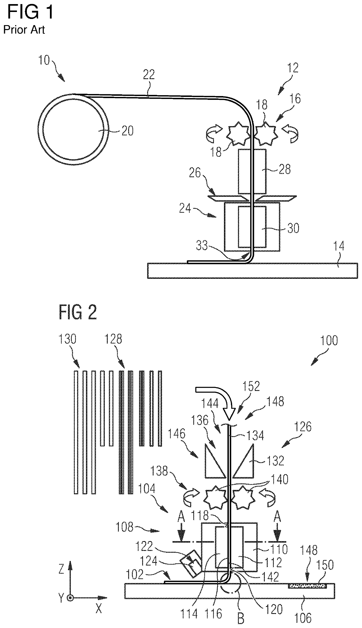
[0116]Reference hereunder is made to FIG. 2 which schematically shows an additive manufacturing device 100. The additive manufacturing device 100 is configured so as to generate a component 102 layer by layer. The component 102 is, in particular, a component of an aircraft. The component 102 can be a plastic-material component, or a fiber-reinforced plastic-material component, or a mixture thereof. The component 102 may also contain metal inserts.

[0117]The additive manufacturing device 100 comprises a printing head 104 which, in a manner known per se, is movable relative to a printing bed 106.

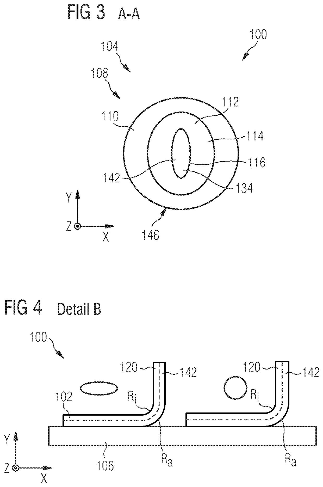
[0118]A plurality of components can be accommodated in the printing head 104. The printing head 104 can comprise an additive manufacturing installation 108. The additive manufacturing installation 108 is configured for generating the component 102 layer by layer on the printing bed 106. The additive manufacturing installation 108 can have a housing 110.

[0119]The additive manufacturing installat...


PUM

PropertyMeasurementUnit
diameteraaaaaaaaaa
diameteraaaaaaaaaa
thicknessesaaaaaaaaaa

Abstract

A method of using solid profile rods instead of the usual filament coils for additive manufacturing methods such as 3D printing for industrial applications such as aircraft manufacturing, and to enable a more rapid production of fiber-composite components. The additive manufacturing device, or the 3D printer which generates the component layer by layer, respectively, comprises a material magazine in which a plurality of profile rods are stored. The profile rods are pre-tailored and are adapted to the component layer by layer. The profile rods, when printing, are successively retrieved from the material magazine and, by way of an infeed installation, guided to the nozzle of the additive manufacturing installation and subsequently applied to the printing bed so as to form the component layer by layer.

Description

CROSS-REFERENCES TO RELATED APPLICATIONS[0001]This application claims the benefit of the German patent application No. 10 2019 108 123.8 filed on Mar. 28, 2019, the entire disclosures of which are incorporated herein by way of reference.FIELD OF THE INVENTION[0002]The invention relates to an additive manufacturing device which is configured for the additive manufacturing of a component. The invention furthermore relates to an additive manufacturing method, and to a profile rod for use in the method.BACKGROUND OF THE INVENTION[0003]The most common 3D printing application uses plastic materials in the so-called fused filament fabrication (FFF) in which a thermoplastic filament is melted and applied to a printing bed. The filament can contain additives or reinforcements. The filament cools and re-solidifies on the printing bed.[0004]The filament is usually provided as a coil which is fitted close to the printing head, or at an immovable position of the 3D printer. The filament herein i...

Claims


Application Information

Patent Timeline
Patent Type & Authority Applications(United States)
IPC IPC(8): B29C64/118B29C64/321B29C64/255
CPCB29C64/321B33Y10/00B29C64/255B33Y30/00B29C64/118B29C64/20B29C64/35B33Y40/20B33Y70/00B33Y70/10
Inventor FASTERT, CLAUSELBRACHT, DIRKBORN, JOHANNESSCHUBERT, KONSTANTIN
Owner AIRBUS OPERATIONS GMBH
Why Eureka
Try Eureka