
Self-powered, self-propelled computer grid with loop topology

a computer grid and loop topology technology, applied in the direction of position/direction control, wind energy generation, underwater vessels, etc., can solve the problems of limiting the development of computing, unable to permit cost-effective harvesting of energy from high-energy areas of the sea, and the time of energy infrastructure becomes the limiting factor on computing development, etc., to achieve the effect of efficient harvesting

Pending Publication Date: 2020-10-08
LONE GULL HLDG LTD
View PDF20 Cites 4 Cited by
  • Summary
  • Abstract
  • Description
  • Claims
  • Application Information

AI Technical Summary

Benefits of technology

[0006]Disclosed are mechanisms, apparatuses, systems, and methods which permit rich, and currently under-utilized, natural and renewable marine energy resources to be efficiently harvested and put to good purpose, offsetting and potentially supplanting a portion of the electrical power generated on land.

Problems solved by technology

Furthermore, as computing becomes so energy-intensive that new energy infrastructure must be built in order to accommodate it, the lead time of energy infrastructure becomes the limiting factor on the development of computing.
Devices for collecting energy from these resources, and deployment configurations thereof, included in the prior art do not permit the cost-effective harvesting of energy from these high-energy areas of the sea.

Method used


Image

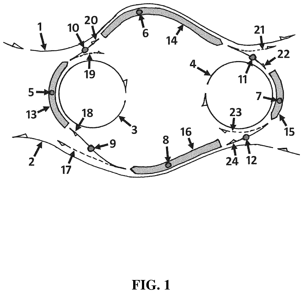
  • Self-powered, self-propelled computer grid with loop topology
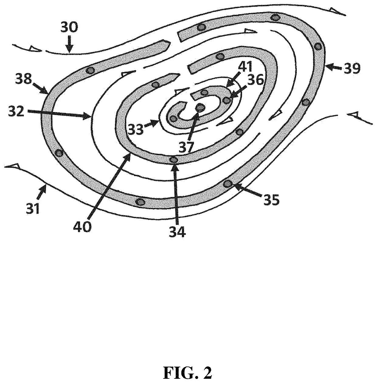
  • Self-powered, self-propelled computer grid with loop topology
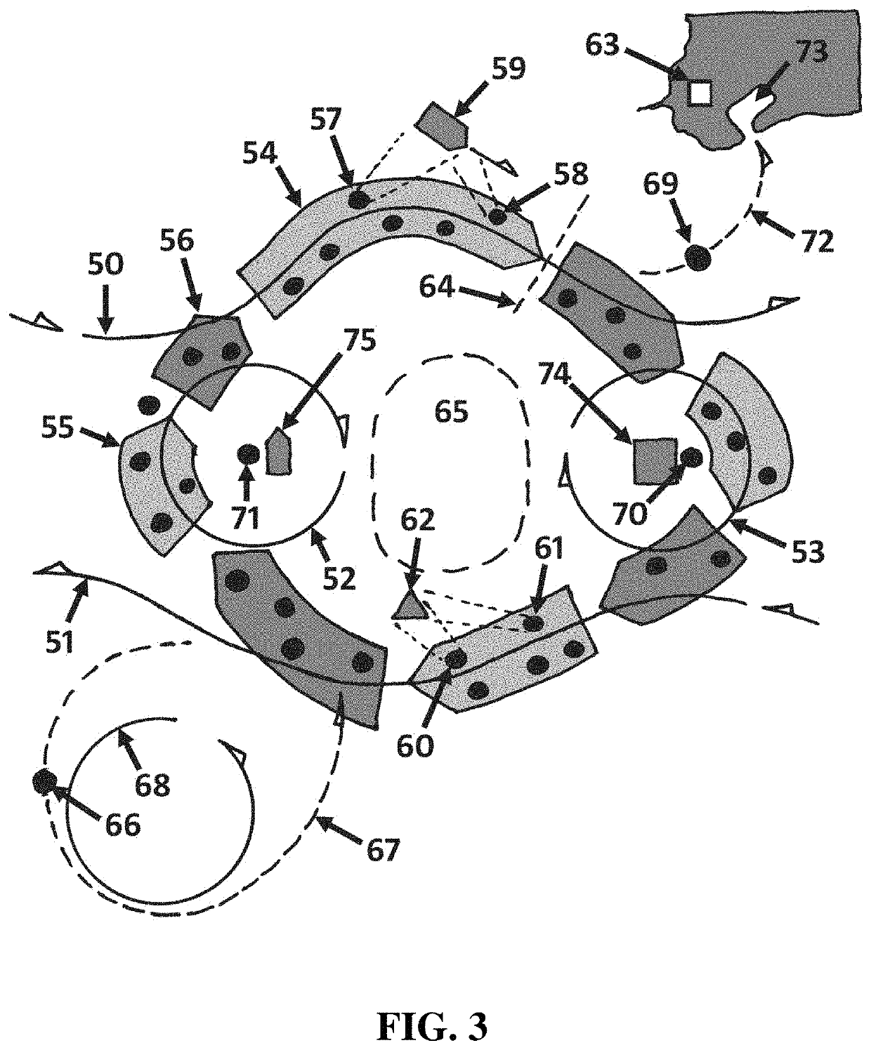
  • Self-powered, self-propelled computer grid with loop topology

Examples


embodiment 530

[0419]Attached to an upper deck 548 of the buoy of the embodiment 530 are rows of antennas, e.g., 537, that form a phased array antenna in which signals driving each individual antenna, e.g., 537, are adjusted by phase so as to direct the resulting beam. Similarly, the phase of the signals received by each antenna are adjusted so as to narrow or constrict the direction from which signals may be received.

[0420]FIG. 38 shows a side perspective view of a type of self-propelled energy harvesting device (an “SPEHD”) which an embodiment of the current disclosure might include.

[0421]A buoyant structure 560, buoy, float, barge, boat, ship, and / or buoyant platform, floats adjacent to an upper surface 561 of a body of water. The buoy 560 has a “v-shaped” hull, a pair of propellers, e.g., 562, and a rudder 563, facilitating the self-propelled movement of the embodiment through the water 561 (e.g., in directions approximately opposite the propeller-generated thrust).

embodiment 560

[0422]An open-bottomed water tube 564 is incorporated within the embodiment 560 near the center of buoy 560 (with respect to a horizontal plane and cross-section) and has a vertical longitudinal axis that is approximately coaxial with a vertical longitudinal axis of the device. Because the bottom 565 of the water tube 564 is open to the water below, water 566 tends to move into, and out of, the water tube. As water oscillates vertically and / or longitudinally within the water tube 564, especially in response to wave motion, a pocket of air (not visible) trapped near the top of the water tube is cyclically compressed and decompressed.

[0423]When the air pocket is compressed, a one-way valve (not visible) allows a portion of the compressed air to flow into a high-pressure accumulator (not visible) within the buoy 560 after which it flows through a tube 567 into a tubular channel 568 within which a turbine (not visible) extracts energy from the flowing air and causes a generator 569 to g...

embodiment 800

[0486]The embodiment 800 floats adjacent to an upper surface 801 of a body of water over which waves pass. The embodiment contains a buoyant, and / or buoy, portion 800 and a depending tubular portion 802. As waves cause the device 800 to move up and down, water within the tube 802 moves up and down as well, causing water to move 803 in and out of the tube 802 through the tube's lower mouth 804. A power take off (PTO) within the device's buoy and / or tube converts a portion of the energy inherent in the movements of water within the device's tube 802 into electrical power. The device illustrated in FIG. 47 uses a piston within the tube to drive a hydraulic PTO. An device similar to the one illustrated in FIG. 47 uses a magnetohydrodynamic PTO to generate electrical power directly from seawater moving up and down within the tube 802. Other devices similar to the one illustrated in FIG. 47 use different mechanisms, methods, and PTOs in order to extract electrical power from the water mov...


PUM


Abstract

An energy-harvesting compute grid includes computing assemblies that cooperate with mobile energy harvesters configured to be deployed on a body of water. The plurality of energy harvesters are positioned on and move adjacent to an upper surface of a body of water, and the locations of the energy harvesters can be monitored and controlled. The wide-spread gathering by the harvesters of environmental data within that geospatial area permits the forecasting of environmental factors, the discovery of advantageous energy-harvesting opportunities, the observation and tracking of hazardous objects and conditions, the efficient distribution of data and / or tasks to and between the harvesters included in the compute grid, the efficient execution of logistical operations to support, upgrade, maintain, and repair the cluster, and the opportunity to execute data-gathering across an area much larger than that afforded by an individual harvester (e.g., radio astronomy, 3D tracking of and recording of the communication patterns of marine mammals, etc.). The computational tasks can be shared and distributed among a compute grid implemented in part by a collection of individual floating self-propelled energy harvesters thereby providing many benefits related to cost and efficiency that are unavailable to relatively isolated energy harvesters, and likewise unavailable to terrestrial compute grids of the prior art.

Description

CROSS-REFERENCES TO RELATED APPLICATIONS[0001]This is a continuation based on U.S. Ser. No. 16 / 248,410, filed Jan. 15, 2019, which claims priority to U.S. Ser. No. 62 / 618,086, Jan. 17, 2018; U.S. Ser. No. 62 / 622,879, Jan. 27, 2018; U.S. Ser. No. 62 / 693,373, Jul. 2, 2018; and U.S. Ser. No. 62 / 774,115, Nov. 30, 2018, the contents of each of which are incorporated by reference herein in their entireties.BACKGROUND[0002]As computing consumes a larger fraction of the world's electricity supply, providers of computing services are becoming some of the largest buyers of energy and the largest funders of energy projects. The question therefore arises how the mammoth parallel computers and compute grids of the future will be powered.[0003]Furthermore, as computing becomes so energy-intensive that new energy infrastructure must be built in order to accommodate it, the lead time of energy infrastructure becomes the limiting factor on the development of computing. The question therefore arises ...

Claims


Application Information

Patent Timeline
Patent Type & Authority Applications(United States)
IPC IPC(8): F03B13/14G05D1/02G05D1/00G01C21/20B63B35/44B63G8/00G06F9/48F03D7/04F03D9/00F03D13/25
CPCH02K7/183F05B2220/708F05B2240/931F05B2260/8211F03D7/048F05B2240/95B63B2035/4466F05B2260/82G05D1/0206B63G8/001B63G2008/004F05B2240/40G01C21/20H02K7/1823G06F9/4881B63B35/44F03D13/25F03B13/14F05B2270/321F03D9/008F05B2270/32G05D1/0055G06F9/5027B63H9/061B63J2003/046B63B2035/442Y02E10/727Y02D10/00Y02E10/72Y02T70/00Y02E10/30F03D13/256
Inventor SHELDON-COULSON, GARTH ALEXANDERMOFFAT, BRIAN LEEPLACE, DANIEL WILLIAM
Owner LONE GULL HLDG LTD
Learn More