Heating, Ventilating, Air Conditioning Fan-On Correction

a technology of air conditioner fan and air ionizer, which is applied in the field of heating, ventilating, and air conditioning (hvac) system, can solve the problem that air ionizer only provides useful work to sanitize the air, and achieve the effect of reducing cooling and heating energy, and eliminating unnecessary or unintentional hvac fans

Active Publication Date: 2020-10-15
LAU JAMES
View PDF0 Cites 8 Cited by
  • Summary
  • Abstract
  • Description
  • Claims
  • Application Information

AI Technical Summary

Benefits of technology

[0054]The present invention provides a Heating, Ventilating, Air Conditioning (HVAC) fan and ultraviolet lamp control solution for an unresolved need to override or supersede a fan-on setting and turning off an ultraviolet (UV) lamp after the HVAC fan is turned off to reduce or eliminate unnecessary or unintentional HVAC fan and ultraviolet lamp energy and also reduce cooling and heating energy caused by outdoor air introduced into the building by an economizer or duct leakage. The present invention provides a HVAC fan-on correction method, the method comprising: detecting that a HVAC fan is controlled by a fan-on setting; determining that the HVAC fan operating time (F6) is greater than a Threshold Fan-on Time (TFT), and performing at least one action selected from the group consisting of: providing a fan-on alarm message, overriding the fan-on setting turning off the HVAC fan, turning off the ultraviolet lamp after the HVAC fan is turned off, and turning on the ultraviolet lamp when the HVAC fan is turned on.

Problems solved by technology

An air ionizer only provides useful work to sanitize the air when the HVAC fan is operating.

Method used


Image

  • Heating, Ventilating, Air Conditioning Fan-On Correction
  • Heating, Ventilating, Air Conditioning Fan-On Correction
  • Heating, Ventilating, Air Conditioning Fan-On Correction

Examples


Embodiment Construction

[0090]The following description is of the best mode presently contemplated for carrying out the invention. This description is not to be taken in a limiting sense, but is made merely for the purpose of describing one or more preferred embodiments of the invention. The scope of the invention should be determined based on the claims.

[0091]Where the terms “about” or “generally” are associated with an element of the invention, it is intended to describe a feature's appearance to the human eye or human perception, and not a precise measurement, or within 10 percent of a stated value. Drybulb temperature measurements at indicated without asterisks and corresponding wetbulb temperatures are indicated by the addition of an asterisk. As noted previously, temperatures in degrees Fahrenheit are indicated by an “F” directly following a number.

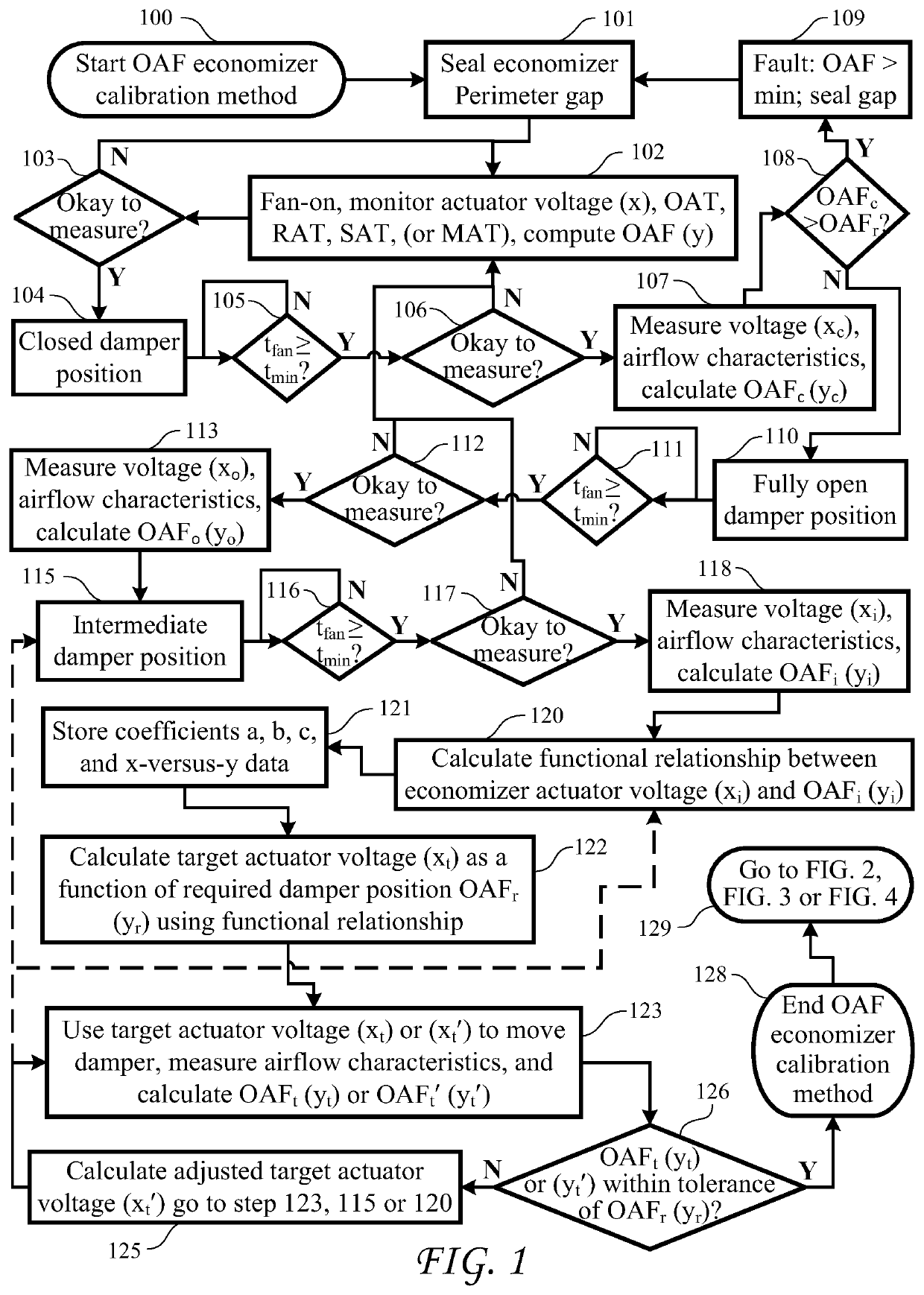
[0092]FIG. 1 shows an Outdoor Air Fraction (OAF) Economizer Controller Calibration (ECC) method for an HVAC system with the HVAC fan-on during occupied or...


PUM


Abstract

A Heating, Ventilating Air Conditioning (HVAC) fan control method comprising: detecting a HVAC fan is controlled by a fan-on setting, determining a HVAC fan-on operating time (F6) is greater than a Threshold Fan-on Time (TFT); and performing at least one action selected from the group consisting of: providing a HVAC fan-on alarm message, overriding the fan-on setting, and turning off the HVAC fan. The method may also include turning off an ultraviolet lamp after the HVAC fan is turned off, and turning on the ultraviolet lamp after the HVAC fan is turned on. Turning off the HVAC fan comprises: turning off the HVAC fan for a variable duration, skipping a scheduled fan-on setting, turning off the HVAC fan based on a call for cooling/heating, turning off the HVAC fan based on an indoor air quality measurement, and turning off the HVAC fan based on a geofencing or occupancy sensor signal.

Description

CROSS-REFERENCE TO RELATED APPLICATIONS[0001]The present application is a Continuation In Part of U.S. patent application Ser. No. 16 / 882,222 filed May 22, 2020, which is a Continuation In Part of U.S. patent application Ser. No. 16 / 869,396 filed May 7, 2020, which is a Continuation In Part of U.S. patent application Ser. No. 16 / 289,313 filed Feb. 28, 2019, which is a Continuation In Part of U.S. patent application Ser. No. 15 / 614,600 filed Jun. 5, 2017, which is a Continuation In Part of U.S. patent application Ser. No. 15 / 358,131 filed Nov. 22, 2016, the present application claiming the priority of the above applications which are incorporated in their entirety herein by reference.BACKGROUND OF THE INVENTION[0002]The present invention relates to a Heating, Ventilating, and Air Conditioning (HVAC) system with economizers.[0003]Known prior art economizers include an economizer frame that connects to a HVAC system cabinet, a supply damper assembly to provide an economizer cooling and...

Claims


Application Information

Patent Timeline
Patent Type & Authority Applications(United States)
IPC IPC(8): F24F11/46F24F11/56F24F11/61F24F11/64F24F11/65F24F11/74F24F11/77G05B19/042
CPCF24F2110/64F24F2110/10F24F2110/12F24F2110/66F24F2110/50F24F11/56F24F11/77F24F11/64F24F11/61F24F2011/0006G05B2219/2614F24F2110/52G05B19/042F24F2140/60F24F2120/10F24F11/46F24F11/74F24F11/65F24F2110/70F24F11/52F24F8/22Y02B30/70
Inventor MOWRIS, ROBERT J.
Owner LAU JAMES
Why Eureka
Try Eureka