Converter circuit, power conversion system, and motor drive apparatus

a technology of converter circuit and power conversion system, which is applied in the direction of control system, motor control in four quadrants, electronic commutation motor control, etc., can solve the problems of high cost and complicated circuitry, and achieve the effect of simple structure and simple circuitry

Inactive Publication Date: 2020-10-15
FANUC LTD
View PDF0 Cites 0 Cited by
  • Summary
  • Abstract
  • Description
  • Claims
  • Application Information

AI Technical Summary

Benefits of technology

[0006]In a power conversion system including a converter circuit and an inverter circuit, a DC voltage equal to or lower than an input rated voltage is to be desirably input to the inverter circuit. For example, a converter circuit serving as a diode rectifier circuit outputs a DC voltage that depends on the magnitude of an AC voltage input from an AC power supply. As another example, in a converter circuit serving as a PWM switching control rectifier circuit, the voltage of the converter circuit on the DC output side may be preferably always boosted to be equal to or higher than the peak value of an AC voltage input from an AC power supply. Therefore, depending on the magnitude of the AC voltage of the AC power supply, some kind of adjustment may be preferably performed for the DC output voltage of the converter circuit to set the DC voltage input to the inverter circuit to an input rated voltage or less. It is a common practice, for example, to place a transformer on the AC input side of a converter circuit and transform an AC voltage input to the converter circuit to step down the DC output voltage of the converter circuit to be equal to or lower than the input rated voltage of an inverter circuit. It is another common practice to place a DC / DC converter circuit (that is different from a converter circuit serving as a rectifier circuit) on the DC output side of a converter circuit and lower the DC output voltage of the converter circuit by the DC / DC converter circuit to obtain a voltage equal to or lower than the input rated voltage of an inverter circuit. Since the AC power supply voltage differs in each country or region, adjustment using a transformer or a DC / DC converter circuit, as described above, is widely performed to use power conversion systems mass-produced based on certain standards. The transformer and the DC / DC converter circuit, however, are physically large, have complicated circuitry, and naturally entail high costs. Therefore, a demand has arisen for a compact, low-cost converter circuit having a simple structure, in a power conversion system including a converter circuit and an inverter circuit and used for a motor drive apparatus.

Problems solved by technology

The transformer and the DC / DC converter circuit, however, are physically large, have complicated circuitry, and naturally entail high costs.

Method used


Image

  • Converter circuit, power conversion system, and motor drive apparatus
  • Converter circuit, power conversion system, and motor drive apparatus
  • Converter circuit, power conversion system, and motor drive apparatus

Examples


first embodiment

[0032]A converter circuit, a power conversion system, and a motor drive apparatus will be described first.

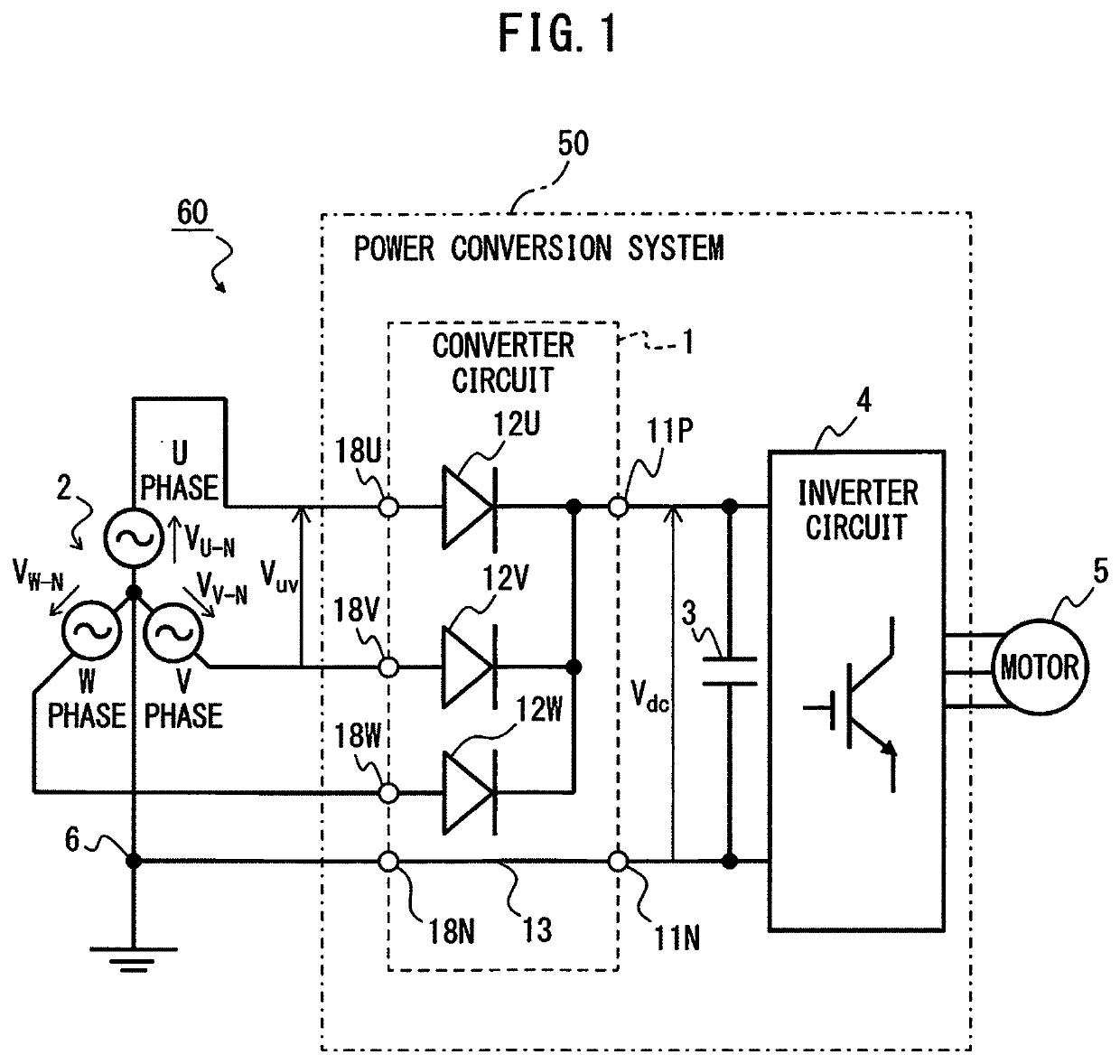
[0033]FIG. 1 is a block diagram depicting a converter circuit, a power conversion system, and a motor drive apparatus according to the first embodiment of the present disclosure.

[0034]The case where a motor 5 is controlled by a motor drive apparatus 60 connected to a polyphase AC power supply 2 will be taken as an example herein. The type of motor 5 is not particularly limited, and may be implemented as, e.g., an AC motor or a DC motor. When the motor 5 is implemented as a DC motor, no inverter circuit 4 is used. When, as illustrated in FIG. 1, the motor 5 is implemented as an AC motor, it may serve as, e.g., an induction motor or a synchronous motor, and the number of phases of the motor 5 is not limited either. Machines equipped with motors 5 include, e.g., a machine tool, a robot, forging machinery, an injection molding machine, industrial machinery, transport machinery, and...

second embodiment

[0060]A converter circuit, a power conversion system, and a motor drive apparatus will be described next.

[0061]FIG. 9 is a block diagram depicting a converter circuit, a power conversion system, and a motor drive apparatus according to a second embodiment of the present disclosure. In the second embodiment, AC reactors 16U, 16V, and 16W are additionally interposed between the anodes of the diodes 12U, 12V, and 12W, respectively, of the converter circuit 1 and the respective phases of the polyphase AC power supply 2 in the first embodiment. In the example illustrated in FIG. 9, since the polyphase AC power supply 2 is implemented as a three-phase AC power supply, the first AC reactor 16U is electrically connected between the U-phase AC terminal 18U and the anode of the first diode 120. The second AC reactor 16V is electrically connected between the V-phase AC terminal 18V and the anode of the second diode 12V. The third AC reactor 16W is electrically connected between the W-phase AC...

third embodiment

[0062]A converter circuit, a power conversion system, and a motor drive apparatus will be described next.

[0063]FIG. 10 is a block diagram depicting a converter circuit, a power conversion system, and a motor drive apparatus according to a third embodiment of the present disclosure. In the third embodiment, a DC reactor 17 is additionally interposed between the positive DC terminal 11P and the cathodes of all the diodes 12U, 12V, and 12W of the converter circuit 1 in the first embodiment. Providing a DC reactor 17 makes it possible to reduce pulsation of a DC voltage output via the positive DC terminal 11P and the negative DC terminal 11N of the converter circuit 1. Since other circuit components are the same as those illustrated in FIG. 1, the same reference numerals denote the same circuit components, and a detailed description thereof will not be given.

[0064]A converter circuit, a power conversion system, and a motor drive apparatus according to a fourth embodiment will be descri...


PUM

PropertyMeasurementUnit
voltagesaaaaaaaaaa
voltagesaaaaaaaaaa
phase voltagesaaaaaaaaaa

Abstract

A converter circuit for converting an AC voltage input from a polyphase AC power supply into a DC voltage and outputting the DC voltage includes a positive DC terminal and a negative DC terminal configured to output the DC voltage, diodes each having its anode electrically connected to a corresponding phase of the polyphase AC power supply, and all having their cathodes electrically connected to the positive DC terminal, and a connection portion electrically connecting a neutral point of the polyphase AC power supply and the negative DC terminal to each other.

Description

BACKGROUND OF THE INVENTION1. Field of the Invention[0001]The present invention relates to a converter circuit, a power conversion system, and a motor drive apparatus.2. Description of the Related Art[0002]In a motor drive apparatus for driving AC motors in a machine tool, forging machinery, an injection molding machine, industrial machinery, or various robots, an AC voltage input from an AC power supply is temporarily converted into a DC voltage, the DC voltage is further converted into an AC voltage, and the AC voltage is applied to and drives the AC motors. Therefore, the motor drive apparatus includes a power conversion system including a converter circuit that rectifies an AC voltage output from an AC power supply into a DC voltage, and an inverter circuit that converts the DC voltage output from the converter circuit into an AC voltage.[0003]As disclosed in, e.g., Japanese Unexamined Patent Publication No. 2000-228883, a power conversion apparatus is known in which three conve...

Claims


Application Information

Patent Timeline
Patent Type & Authority Applications(United States)
IPC IPC(8): H02M7/155H02P6/08
CPCH02M7/1557H02M7/06H02P6/085H02P27/08H02P23/06H02M1/007H02M5/4585
Inventor FUJII, SHOUTA
Owner FANUC LTD
Why Eureka
Try Eureka