
Process fluid lubricated pump

a technology of fluid lubrication and pump shaft, which is applied in the direction of fluid removal, engine fuction, couplings, etc., can solve the problems of reducing the overall dimension of the pump, limiting the motor speed to about 6000 rpm, and reducing the design of such pumps. , to achieve the effect of reducing the overhang increasing the stability of the pump shaft, and reducing the susceptibility to unbalan

Inactive Publication Date: 2020-10-29
SULZER MANAGEMENT AG
View PDF0 Cites 2 Cited by
  • Summary
  • Abstract
  • Description
  • Claims
  • Application Information

AI Technical Summary

Benefits of technology

The patent text discusses the importance of reliability and minimal damage in subsea pumps. The text also introduces a design that has a compact design and reduces the size of the pump. The technical effects of this design are improved reliability and performance of subsea pumps.

Problems solved by technology

The design of such pumps can be challenging, in particular because these pumps operate in a difficult subsea environment for a long time period with as little maintenance and service work as possible .
Indeed, these viscous losses limit the motor speed to about 6000 rpm.
Although such mechanical seals are widely spread within the technology of centrifugal pumps, they are somewhat problematic for subsea applications because they are quite complicated and usually require additional equipment, which is often considered as a drawback for subsea applications.
Beside the reduced overhang of both the drive shaft and the pump shaft, this design is very compact and reduces the overall dimension of the pump.

Method used


Image

  • Process fluid lubricated pump
  • Process fluid lubricated pump
  • Process fluid lubricated pump

Examples


first embodiment

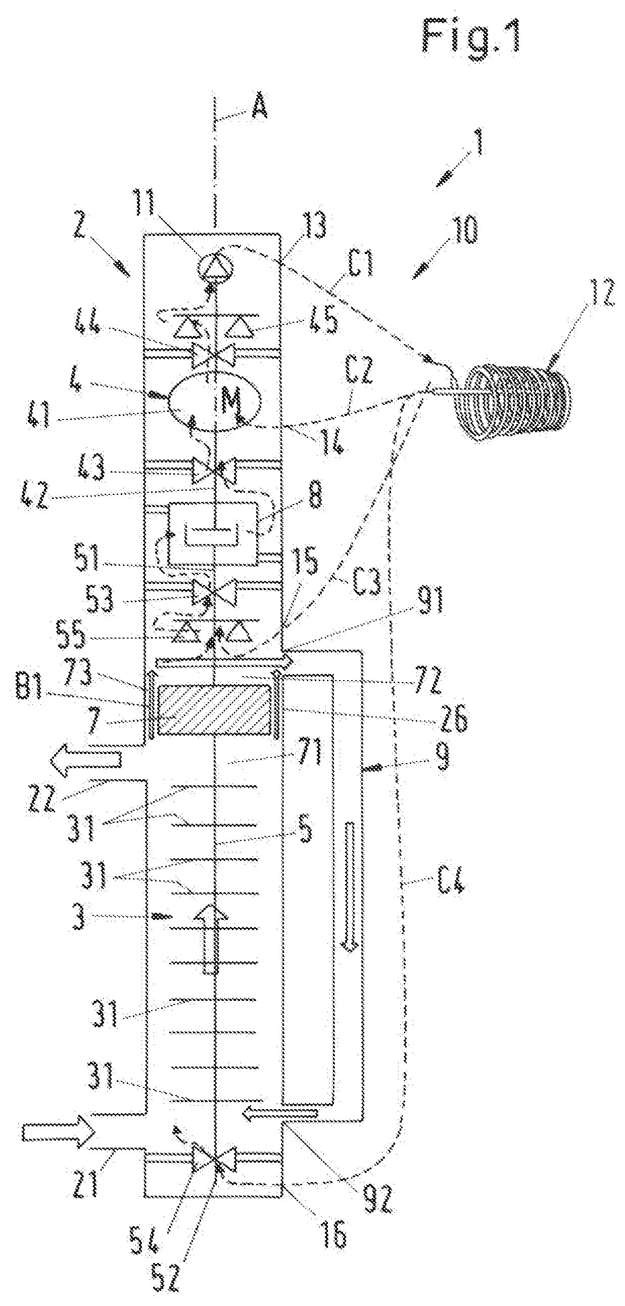
[0044]FIG. 1 shows a schematic cross-sectional view of a process fluid lubricated pump according to the invention, which is designated in its entity with reference numeral 1. The pump 1 is designed as a centrifugal pump for conveying a process fluid and has a common housing 2, a pump unit 3 and a drive unit 4. Both the pump unit 3 and the drive unit 4 are arranged within the common housing 2. The common housing 2 is designed as a pressure housing, which is able to withstand the pressure generated by the pump 1 as well as the pressure exerted on the pump 1 by the environment. The common housing 2 can comprise several housing parts, e.g. a pump housing and a drive housing, which are connected to each other to form the common housing 2 surrounding the pump unit 3 and the drive unit 4. The common housing 2 is a hermetically sealed pressure housing preventing any leakage to the external environment.

[0045]In the following description reference is made by way of example to the important ap...

second embodiment

[0103]FIG. 5 shows a schematic cross-sectional view of a process fluid lubricated pump 1 according to the invention.

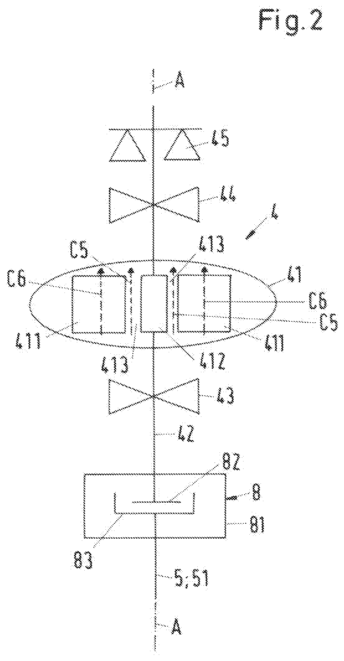
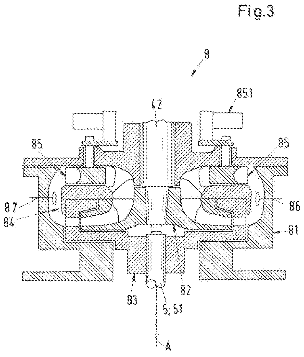
[0104]In the following description of the second embodiment of the process fluid lubricated pump 1 only the differences to the first embodiment are explained in more detail. The explanations with respect to the first embodiment are also valid in the same way or in analogously the same way for the second embodiment. Same reference numerals designate the same features that have been explained with reference to the first embodiment or functionally equivalent features. In particular, the drive unit explained with reference to FIG. 2 as well as the torque converter explained with reference to FIG. 3 can also be used for the second embodiment.

[0105]Compared to the first embodiment, it is the main difference, that the second embodiment of the pump 1 does not comprise an external cooling loop 10. The pump bearings 53, 54, 55 as well as the drive unit 4 comprising the electric ...

third embodiment

[0111]FIG. 6 shows a schematic cross-sectional view of a process fluid lubricated pump 1 according to an embodiment of the invention.

[0112]In the following description of the third embodiment of the process fluid lubricated pump 1 only the differences to the first and the second embodiment are explained in more detail. The explanations with respect to the first embodiment and with respect to the second embodiment are also valid in the same way or in analogously the same way for the third embodiment. Same reference numerals designate the same features that have been explained with reference to the first and the second embodiment or functionally equivalent features. In particular, the drive unit explained with reference to FIG. 2 can also be used for the third embodiment, and the external cooling loop 10 (FIG. 1) as well as the cooling loop 10′ (FIG. 4) can also be used for the third embodiment.

[0113]The third embodiment is similar to the second embodiment (FIG. 5). Compared to the se...


PUM


Abstract

A process fluid lubricated pump for conveying a process fluid, includes a common housing, a pump unit arranged in the common housing, a drive unit arranged in the common housing, and a hydrodynamic coupling. The common housing includes a pump inlet and a pump outlet for the process fluid. The pump unit includes at least one impeller configured to convey the process fluid from the pump inlet to the pump outlet, and a pump shaft, on which the impeller is mounted. The drive unit includes a drive shaft configured to drive the pump shaft, and an electric motor configured to rotate the drive shaft about an axial direction. The hydrodynamic coupling is configured to hydrodynamically couple the drive shaft to the pump shaft by a transmission fluid, and is configured to receive the process fluid as the transmission fluid.

Description

CROSS-REFERENCE TO RELATED APPLICATION[0001]This application claims priority to European Patent Application No. 19170570.6, filed Apr. 23, 2019, the content of which is hereby incorporated herein by reference.BACKGROUNDField of the Invention[0002]The invention relates to a process fluid lubricated pump for conveying a process fluid.Background Information[0003]Conventional process fluid lubricated pumps for conveying a process fluid are used in many different industries. One example is the oil and gas processing industry, where process fluid lubricated pumps are designed, e.g. as multiphase pumps for conveying hydrocarbon fluids, for example for extracting the crude oil from the oil field or for transportation of the oil / gas through pipelines or within refineries. Another application of process fluid lubricated pumps in the oil and gas industry is the injection of a process fluid, in most cases water and in particular seawater, into an oil reservoir. For such applications, the pumps ...

Claims


Application Information

Patent Timeline
Patent Type & Authority Applications(United States)
IPC IPC(8): F04D13/02F04D13/08F04D29/58E21B43/20
CPCE21B43/20F16D33/18F04D13/022F04D29/586F05B2260/232F04D13/08F05B2260/406F04D29/5806F04B9/00F04B39/00F04D13/06F04D29/046F04D29/669F04D13/086F04D1/06F04D29/0473F04D29/0416
Inventor FELIX, THOMASBOURNE, MATTHEWGASSMANN, SIMONDE RAEVE, KAREL
Owner SULZER MANAGEMENT AG
Learn More