
Rotating electric machine drive unit

a technology of electric machines and drive units, which is applied in the manufacture of stator/rotor bodies, electric propulsion mounting, and vehicle sub-unit features, etc., can solve the problems of increasing and achieve the effect of reducing the size of the rotating electric machine drive units

Active Publication Date: 2020-11-12
HONDA MOTOR CO LTD
View PDF0 Cites 1 Cited by
  • Summary
  • Abstract
  • Description
  • Claims
  • Application Information

AI Technical Summary

Benefits of technology

The invention reduces the size of the rotating electric machine drive unit.

Problems solved by technology

However, the rotating electric machine drive unit disclosed in WO 2016 / 121032 has a problem that the size of the rotating electric machine drive unit is increased because the power control device is disposed above the generator and the motor.

Method used


Image

  • Rotating electric machine drive unit
  • Rotating electric machine drive unit
  • Rotating electric machine drive unit

Examples


Embodiment Construction

[0028]Hereinafter, an embodiment of a hybrid vehicle equipped with a rotating electric machine drive unit of the invention will be described with reference to the accompanying drawings.

[0029]

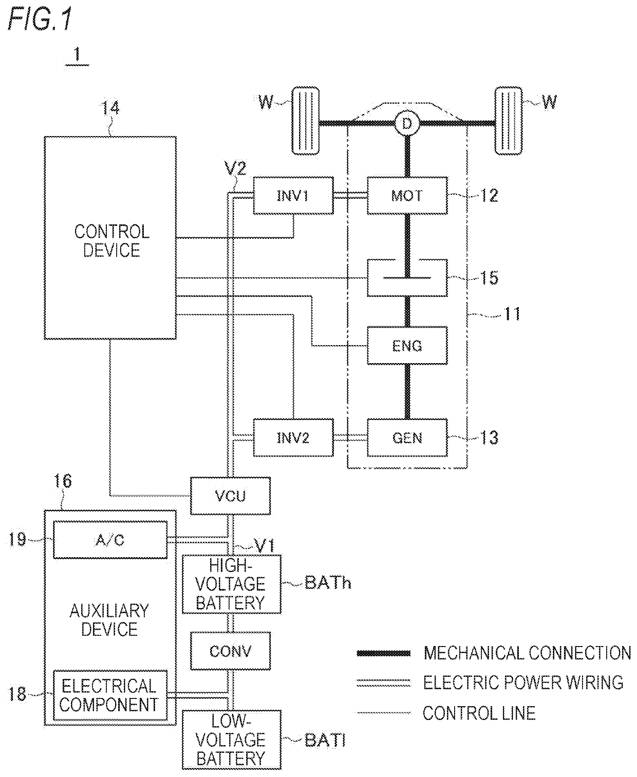
[0030]A hybrid vehicle 1 basically includes a driving device 11, a high-voltage battery BATh, a converter CONV, a low-voltage battery BATl, a voltage control unit VCU, a first inverter INV1, a second inverter INV2, and a control device 14.

[0031]In FIG. 1, a thick solid line indicates a mechanical connection, a double solid line indicates an electric power wiring, and a thin solid line indicates a control line (including a signal line).

[0032]The driving device 11 includes a first rotating electric machine 12 (MOT) and a second rotating electric machine 13 (GEN), each of which is a three-phase embedded magnet structure rotating electric machine that is vector-controlled, an engine ENG, a driving force transmission state switching unit 15, and a speed reducer D.

[0033]The driving force transmission ...


PUM


Abstract

A rotating electric machine drive unit includes a first rotating electric machine, a second rotating electric machine, a rotating electric machine housing, a power control unit having a first power conversion unit and a second power conversion unit, a first connecting member electrically connecting the first rotating electric machine and the first power conversion unit, and a second connecting member electrically connecting the second rotating electric machine and the second power conversion unit. When viewed from a rotation axis direction of the first rotating electric machine and the second rotating electric machine, the rotating electric machine accommodation portion of the rotating electric machine housing includes a bulging portion bulging outward between the first connecting member and the second connecting member, and the first rotating electric machine is accommodated in the rotating electric machine housing such that a part of the first rotating electric machine is located in the bulging portion.

Description

CROSS-REFERENCE TO RELATED APPLICATIONS[0001]This application is based on and claims priority under 35 USC 119 from Japanese Patent Application No. 2019-089098 filed on May 9, 2019.TECHNICAL FIELD[0002]The present invention relates to a rotating electric machine drive unit mounted on an electric vehicle or the like.BACKGROUND ART[0003]In recent years, a rotating electric machine drive unit is mounted on an electric vehicle or the like. For example, in WO 2016 / 121032, a rotating electric machine drive unit which includes a generator capable of generating electricity by receiving power from an engine, a motor which drives a wheel, a case which accommodates the generator and the motor, and a power control device which controls the generator and the motor has been disclosed. In the rotating electric machine drive unit of WO 2016 / 121032, the generator and the motor are juxtaposed on the same axis and a power control device is mounted on a case.[0004]In recent years, this type of a rotati...

Claims


Application Information

Patent Timeline
Patent Type & Authority Applications(United States)
IPC IPC(8): H02K7/00H02K11/33H02K5/04B60K6/26B60K6/405H02K15/02
CPCB60Y2400/61H02K7/006H02K11/33B60K6/26B60K6/405H02K5/04H02K15/02B60K1/00
Inventor WAKABAYASHI, RYUTASUZUKI, YUTO
Owner HONDA MOTOR CO LTD
Features
  • Generate Ideas
  • Intellectual Property
  • Life Sciences
  • Materials
  • Tech Scout
  • Unparalleled Data Quality
  • Higher Quality Content
  • 60% Fewer Hallucinations
Learn More