Water dispensing station

a technology for dispensing stations and water bottles, which is applied in the direction of liquid dispensing, liquid flow controllers, packaging, etc., can solve the problems of reducing the energy efficiency of the chiller, splashing and overfilling errors, and increasing the overall dimensions of the chiller, so as to increase the chilled water capacity of the drink dispenser, improve the taste of alkaline water, and reduce the temperature

Active Publication Date: 2020-11-19
PEPSICO INC
View PDF0 Cites 15 Cited by
  • Summary
  • Abstract
  • Description
  • Claims
  • Application Information

AI Technical Summary

Benefits of technology

[0018]A number of features are provided in an improved beverage drink station. These improvements include, but are not limited to, a drink station having an alkaline filter cartridge in fluid communication with an ambient temperature water line to dispense alkaline water at a spigot on the dispenser. A chilled water line is in fluid communication with the same spigot, so a mixture of chilled water and alkaline water is provided at the spigot to improve the taste of the alkaline water by slightly reducing its temperature. A hot water tank with heater is located below the spigot so hot water flows upward for dispensing from the spigot to provide hot water at the spigot. A vent line between the hot water tank and spigot help hot water to flow from the spigot, back to the hot water tank and avoid heating the spigot. An external carbon dioxide gas tank provides carbonation to a chilled line of sparkling or carbonated water, and in-line carbonators, immersed in a water-bath that is cooled down by the refrigeration system, provide supplemental carbonation to produce different carbonation levels at the spigot. A figure eight evaporator coil provides two cylindrical ice-banks and two drinking water chiller water coils to increase the chilled water capacity of the drink dispenser. Up to two submersible agitator pumps are used to create a spherical flow path in the opposing top and bottom ends of the chilled water bath to control the water bath temperature, with a drinking water temperature sensor controlling the agitators.
[0030]In further variations, the water-bath and ice-bank refrigeration device has the first splitter for the chilled water line and the carbonated water line located inside the chilled water bath during use of the apparatus. Additionally, a first temperature sensor may be placed in electrical communication with the controller and positioned within the chilled water reservoir at a location selected to contact the ice bank along a majority of the length of the sensor during use of the apparatus. The temperature sensor is also in electrical communication with the control module. By measuring the resistivity values that differ significantly between water and ice, the temperature sensor is able to recognize when ice has grown, sends a signal to the electronic control module so that the power to the compressor and fans of the dispenser's refrigeration system is interrupted. The evaporator coils stop freezing water and the growth of ice is interrupted so as to avoid the total freezing of the water inside the chilled water reservoir and of the drinking water inside the stainless steel chiller coil and inside the pipes and connections immersed in the water-bath of the chiller.
[0059]Still further variations of this beverage dispensing apparatus include a water deflector in the water inlet port, positioned at the bottom of the hot water reservoir And in fluid communication with a hot water valve, wherein the water deflector deviates the flow path of the incoming water when the hot water valve is open, so as to direct the incoming water towards the heater in order to avoid inlet water to directly flow through the control tube and out, without first mixing with the hot water inside the hot water reservoir, during use of the dispensing apparatus. Still further variations may include a protective stainless-steel shirt around the heater to avoid scale deposit to reduce the thermal efficiency of the heater.
[0062]In still further variations, the agitator pump has a plurality of ports oriented to direct the outflow path towards the ice-bank and the evaporator coil, but away from temperature sensors inside the chilled water reservoir. The outlet tubes are preferably connected to the outlet ports bringing the water flow from the agitator pump outlets to the ice-bank, so as to avoid the outlet water path accidentally flowing to and around the temperature sensors inside the water bath.
[0067]There is also provided a cup alignment device for a drink dispenser. The drink dispenser has a housing, a spigot for dispensing at least one consumable liquid, a cup support below the spigot and upon which a beverage cup may be placed to receive the liquid dispensed from the spigot and a housing wall located between the spigot and cup support and behind a vertical line between the cup support and the spigot. An illuminated light bar is connected to the housing wall and extends along a vertical path between the spigot and the cup support so that a user can visualize the path of the liquid as it is dispensed from the spigot into a cup resting on or above the cup support. A plastic shield covers the light bar is also connected to the housing wall and extends along the path to shield the light bar from the liquid during use of drink dispenser.

Problems solved by technology

While current art carbonated beverage dispensers use a pressurized canister to combine carbon dioxide gas with water, the space occupied by such vessel under pressure increases the overall dimensions of its chiller and reduces the energy efficiency of its chiller.
Thus, during installation and setup of a dispenser, the installer or the user must fill manually the chilled water reservoir with large volumes of water and associated spilling, splashing and overfilling errors.
When the ice growth is such that it touches the temperature sensor then if the compressor does not stop working the entire water-bath inside the chiller might freeze-up and, consequently, the drinking water that flows inside a stainless steel drinking water chill water coil immersed inside the chiller reservoir whose water bath freezes up completely and cannot be dispensed.
Water dispensers with evaporator cooling coils immersed in the chilled water reservoirs provide a limited supply of cooled water contained in the dispenser, that supply may be depleted during periods of high demand.
If hot water remains in the outlet line between the tank and the spigot the temperature of the water in the line will decrease over time and when the spigot is opened to dispense hot water again, the hot water dispensed from the spigot would have an inconvenient lower temperature because it will be mixed with the cooler water that has remained in the outlet line.
Hot water tanks for water dispensers have temperature sensors that shut off power to the electrical resistance heater when steam is generated because that indicates the hot water reservoir is out of water or low on water, and such heaters avoid steam because the steam temperature can result in dispensing water that is too hot.
Electrical resistance heaters for hot beverage dispensers may overheat when due to the evaporation of water over a certain period of time of no use, the water level in the hot water reservoir becomes too low so that part of the resistance heater is no longer covered with water.

Method used


Image

  • Water dispensing station
  • Water dispensing station
  • Water dispensing station

Examples


Embodiment Construction

[0114]As used herein, the relative terms upstream and downstream refer to the direction in which fluid flows through the various parts and fluid connections. The fluid generally flows downstream from the building water line, to the spigot, and upstream in the opposite direction.

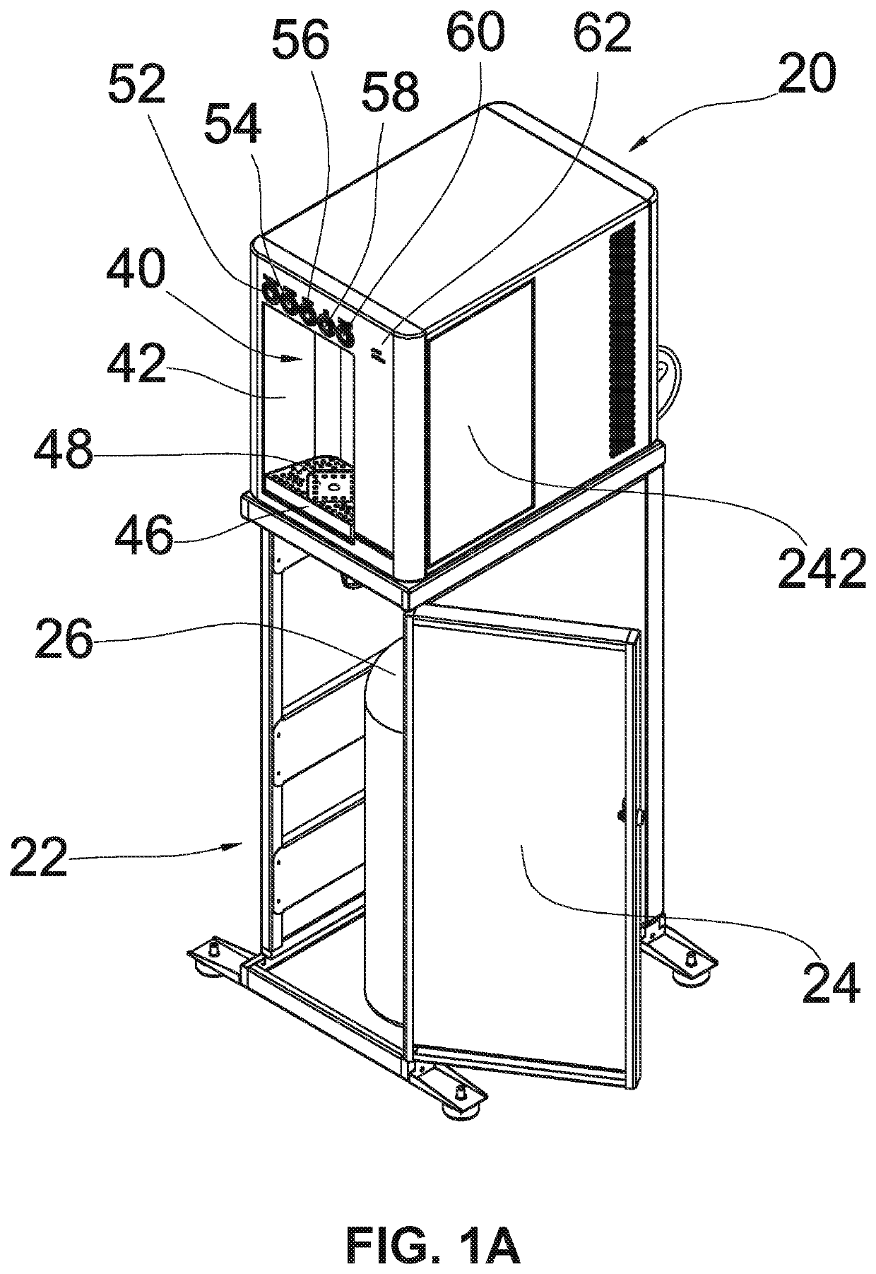
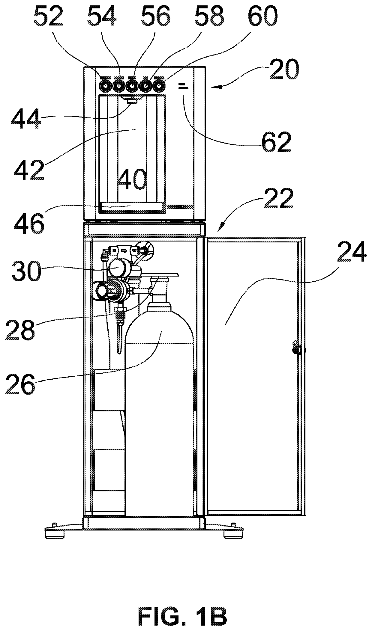
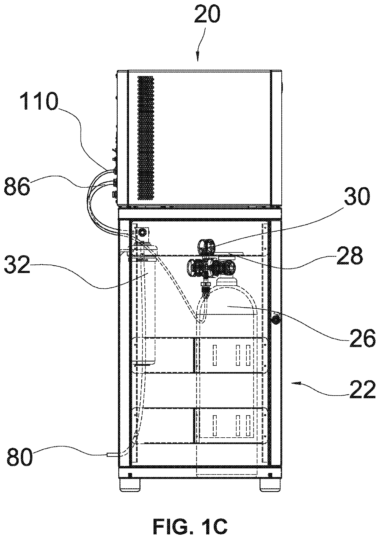
[0115]As used herein, the following part numbers refer to the following parts: 20—drink station; 22—cabinet-stand; 24—door; 26—carbon dioxide gas tank; 28—shut-off valve of the carbon-dioxide gas tank; 30—carbon dioxide gas pressure and flow regulator; 32—water filter; 40—filling / dispensing area; 42—sidewall of the dispensing area; 44—spigot / nozzle; 46—drain pan; 48—drain grate; 50—drain pipe; 51—drain exit port; 52—carbonated water button; 54—alkaline water button; 56—chilled water button; 58—hot water button; 60—auto-fill button; 62—indicator lights; 64—controller; 68: dotted line simulating the housing of a drink station; 70—compressor; 72—freezer expansion line; 74—chilled water reservoir; 76—insulation; ...


PUM


Abstract

A drink station is provided with an alkaline filter cartridge in fluid communication with an ambient temperature water line provide alkaline water, and with a chilled water mixed with the alkaline water at a spigot to provide chilled alkaline water. A hot water heating element is located below the spigot so hot water flows upward for dispensing from the spigot, with a vent line between the heating element and spigot helping hot water to flow from the spigot to the heating element. A refrigeration system and a carbonation system is also provided. The refrigeration system uses the ice-bank technology. A submersible agitator pump improves heat exchanged between ice-bank and water by forced convection. The agitator pump operating based on the temperature of the drinking water. A figure eight evaporator coil can provide two cylindrical ice banks and two chilled water coils to increase the chilled water capacity.

Description

CROSS-REFERENCE TO RELATED APPLICATIONS[0001]This application claims priority to U.S. Application Ser. No. 63 / 000,652 filed Apr. 7, 2020, and U.S. Application Ser. No. 62 / 849,796 filed May 17, 2019, the full disclosures of which are incorporated herein by reference.STATEMENT RE:FEDERALLY SPONSORED RESEARCH / DEVELOPMENT[0002]Not applicableBACKGROUND[0003]Water dispensers of different sizes and features are nowadays available in homes, offices and restaurants. But there are several beverages that current dispensers do not dispense and there is thus a need for dispensers that dispense a wider and different variety of waters with different chemical characteristics, such as alkaline waters, or water at different temperatures with different carbonation levels.[0004]Some water dispensers typically provide carbonated water by mixing carbon-dioxide gas with chilled water that is injected at high pressure—using a pump—inside a pressurized canister (i.e., a metal vessel under pressure). When th...

Claims


Application Information

Patent Timeline
Patent Type & Authority Applications(United States)
IPC IPC(8): B67D1/00B67D1/08B67D1/12B67D1/10
CPCB67D1/0058B67D1/10B67D1/0888B67D1/0855B67D1/0895B67D1/004B67D1/1279B67D1/0017B67D1/0859B67D1/0864B67D2210/00047B67D1/0875B67D1/007
Inventor FANTAPPIÉ, GIANCARLOMACRELLINO, DIEGO
Owner PEPSICO INC
Why Eureka
Try Eureka