
Method and device for automatically drawing structural cracks and precisely measuring widths thereof

a technology of structural cracks and widths, applied in the field of structure detection and evaluation, can solve the problems of more human intervention, mainly observed cracks, and difficult to determine whether it is a crack according to features identified by a conventional algorithm, and achieve the effects of high accuracy, high recall, and high precision

Active Publication Date: 2020-11-19
SOUTHEAST UNIV
View PDF0 Cites 31 Cited by
  • Summary
  • Abstract
  • Description
  • Claims
  • Application Information

AI Technical Summary

Benefits of technology

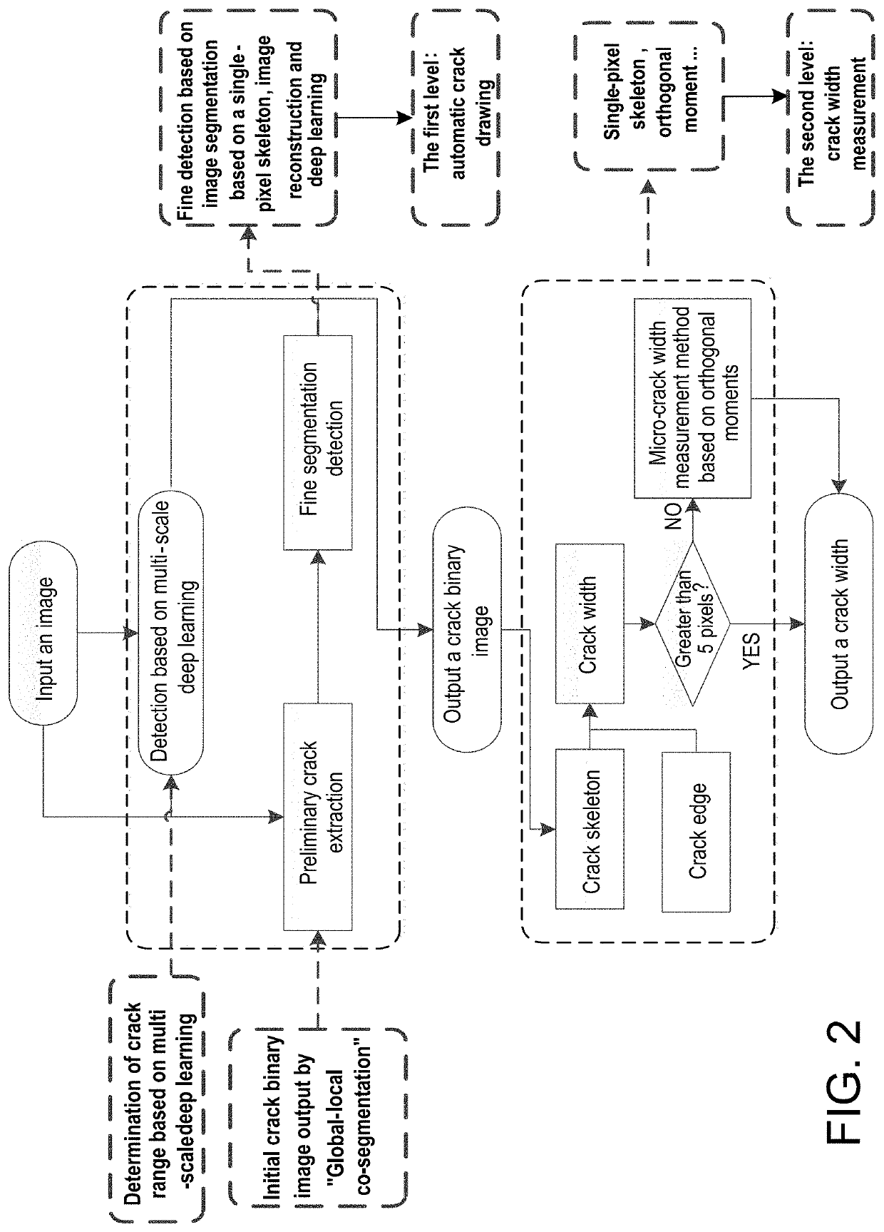
The invention is a method and device that solves the problem of slow and inaccurate detection of structural cracks and their widths in images. It allows for the automated and precise drawing of cracks with high accuracy and recall. Additionally, it can measure the widths of both macro and micro-cracks smaller than 5 pixels in the image.

Problems solved by technology

However, at present, cracks are mainly observed manually, and drawn by a person with interrupting an experiment, and widths of the cracks are measured by manually attaching a crack width gauge to the surface of a structure.
Manually drawing cracks and measuring crack widths with a crack width gauge affects the progress of an experiment due to low efficiency as well as a waste of time and energy, and also lead to a detection result of great personal error.
CN 105719283 are all based on conventional image processing algorithms, however, as the background and features of a crack have considerable variability and complexity, it is difficult to determine whether it is a crack according to features identified by a conventional algorithm.
Moreover, a conventional algorithm tends to require more human intervention, thereby resulting in a low automation level.
CN 106910186A discloses a method for detecting and locating bridge cracks based on CNN deep learning, which can hardly meet the requirements for detecting cracks of different widths in an image due to adopting CNN templates of only 16 pixels in size, and cannot output binary images of cracks accurate to pixel level.
Therefore, this method has disadvantages such as limited performance of classifying, poor sensitivity of an identification result to details in an image, and a detection result of inadequate precision due to a fuzzy crack edge.
The method can hardly be applied to real projects.
Moreover, all conventional crack width measurement methods based on digital image processing calculate crack width as the distance between two pixels, and thus have great limitations.
However, for micro-cracks (smaller than 5 pixels) in images, these methods have great identification errors and can hardly meet requirements for measurement precision.
The method for manually drawing cracks is time-consuming and laborious, and has a great error in measurement of crack width.
Moreover, there are still great defects in crack detection based on image processing.
These defects are specifically as follows: (1) the conventional automatic crack drawing technology based on image processing tends to require excessive human interference, so that the automation level is low and cracks cannot be effectively distinguished from noise interferences, and although the existing image crack identification technology based on deep learning has achieved some success, it still cannot meet requirements for automatically and precisely drawing a crack; and (2) the calculated width of a micro-crack in an image is of great error, and it needs to sacrifice the size of the field of view to meet requirements for detection precision.
Because concrete cracks are complex and diversified in morphology, single-scale deep learning often cannot meet requirements for detecting cracks of different widths in an image, and crack information in an image can be easily missed in the analysis based on detection results of single-scale deep learning.
Conventional methods for calculating crack widths, which calculate the distance between two pixels by “pixel counting”, works badly in calculating the width of a crack less than 5 pixels.

Method used


Image

  • Method and device for automatically drawing structural cracks and precisely measuring widths thereof
  • Method and device for automatically drawing structural cracks and precisely measuring widths thereof
  • Method and device for automatically drawing structural cracks and precisely measuring widths thereof

Examples


example 1

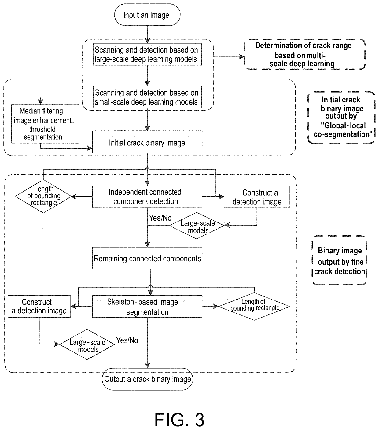
[0072]A method for automatically drawing structural cracks As shown in FIG. 3, the method for automatically drawing structural cracks comprises the following steps: 1) detecting, by a crack detection method based on multi-scale deep learning, a crack range in an image using multi-scale deep learning to ensure that no crack information is missed for subsequent work; 2) extracting, by a preliminary crack extraction method of “global-local co-segmentation” based on deep learning, median filtering and Hessian matrix-based linear enhancement, full information of both macro-cracks and micro-cracks in the image to ensure a detection result of high recall; and 3) effectively removing, by a fine crack detection method based on deep learning, image segmentation and image reconstruction, noise from the result to ensure a detection result of high accuracy and precision. The crack detection method based on multi-scale deep learning in step 1) is specifically as follows: Because concrete cracks a...

example 2

[0098]A method for precisely measuring crack widths based on a single-pixel crack skeleton and Zernike orthogonal moments Conventional methods for calculating crack widths, which calculate the distance between two pixels by “pixel counting”, works badly in calculating the width of a crack less than 5 pixels. Therefore, for cracks smaller than 5 pixels in images, the present invention proposes a method for calculating crack widths based on a single-pixel skeleton and Zernike orthogonal moments, as shown in FIG. 6.

[0099]The method for calculating crack widths based on a single-pixel skeleton and Zernike orthogonal moments utilizes a single-pixel skeleton to determine a rotation angle for an image. The image at this point is rotated, symmetrized and mirrored to obtain two images symmetrical with respect to the y coordinate axis. The second-order orthogonal moment A′20 and the fourth-order orthogonal moment A′40 are calculated respectively for the two symmetrical images by utilizing Ort...

example 3

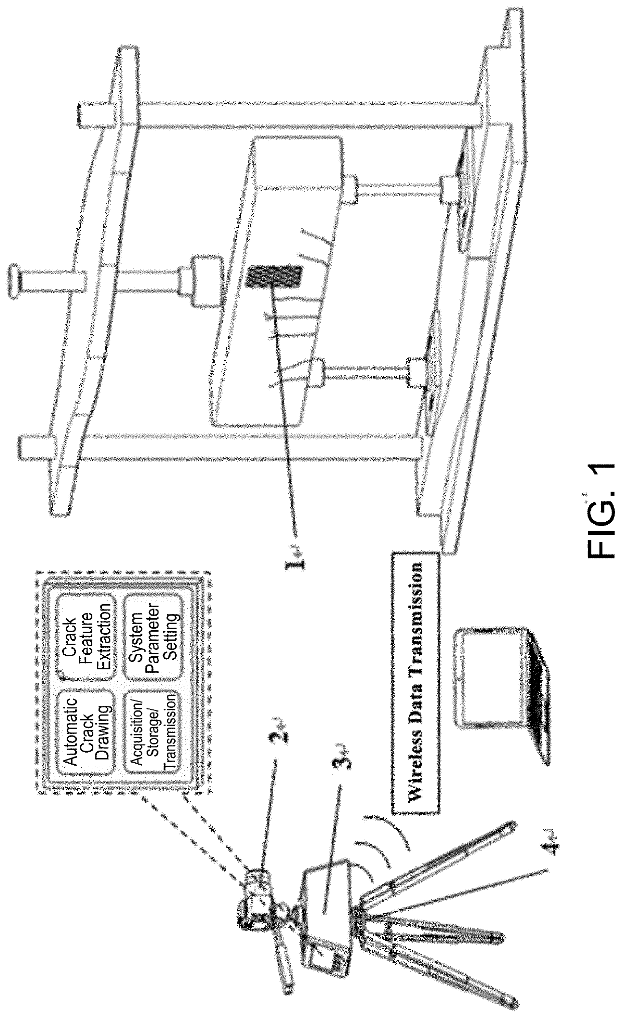
[0104]A device for automatically drawing cracks of a concrete specimen and measuring widths thereof in a laboratory As shown in FIG. 1, the device comprises an image calibration module 1, an image acquisition module 2, an image processing system 3, and a camera tripod 4.

[0105]The device for automatically drawing structural cracks and precisely measuring widths thereof can rapidly and automatically draw structural cracks on a surface and precisely measure crack widths.

[0106]The image calibration module 1 is configured to correct the pose of a camera, calculate the resolution of an image, and paste a plurality of manually-printed checkerboards with a known size on the surface of a concrete specimen; the image acquisition module 2 composed of a single lens reflex camera is mainly configured to acquire a high-resolution image of the concrete specimen for image processing in the next step; and the image processing system 3 is embedded with an automatic crack drawing algorithm module, a c...


PUM


Abstract

The present invention discloses a method and device for automatically drawing structural cracks and precisely measuring widths thereof. The method comprises a method for automatically drawing cracks and a method for calculating widths of these cracks based on a single-pixel skeleton and Zernike orthogonal moments, wherein the method for automatically drawing cracks is used to rapidly and precisely draw cracks in the surface of a structure, and the method for calculating widths of these cracks based on a single-pixel skeleton and Zernike orthogonal moments is used to calculate widths of macro-cracks and micro-cracks in an image in a real-time manner.

Description

BACKGROUNDTechnical Field[0001]The present invention relates to the field of structure detection and evaluation, and in particular to a method and device for detecting structural cracks on a surface based on digital image processing.Description of Related Art[0002]In the field of civil engineering structure, the test for bearing capacity of a new material or structure is one of the experimental methods that are most widely used. Besides structural response indexes such as structural strain and deformation, the development of a structural crack, having a clear correspondence to the bearing capacity of a structure, is an important part of a structural bearing capacity test. However, at present, cracks are mainly observed manually, and drawn by a person with interrupting an experiment, and widths of the cracks are measured by manually attaching a crack width gauge to the surface of a structure. In addition, crack condition is one of the main indexes for periodic structure inspection, l...

Claims


Application Information

Patent Timeline
IPC IPC(8): G06T7/00G01B11/02G01N33/38G06T7/80G06T7/62G06T7/70G06T5/00G06T7/136G06T5/20G06T11/00
CPCG06T7/0004G06T5/20G06T2207/30244G06T5/002G06T2207/30132G06T7/62G06T11/00G01B11/022G06T7/80G01N33/383G06T7/136G06T7/70G06T7/0002G06T7/12G06T7/13G06T7/60G06T2207/20032G06T7/155G06T7/181G06T2207/10004G06T2207/20016G06T2207/20021G06T2207/20044G06T2207/20081G06T2207/20084G06T2207/20192G06T2207/30204G06T5/70
Inventor ZHANG, JIANNI, FUTAO
Owner SOUTHEAST UNIV
Learn More