A method for protecting an x-ray source and an x-ray source

Active Publication Date: 2020-11-19
EXCILLUM
View PDF0 Cites 1 Cited by
  • Summary
  • Abstract
  • Description
  • Claims
  • Application Information

AI Technical Summary

Benefits of technology

[0065]The pressure of the collected liquid is raised to a suction side pressure (inlet pressure) for the high-pressure pump, in a second portion of the recirculating path located between the collecting arrangement and the high-pressure pump in the flow direction (i.e. during normal operation of the system, liquid flows from the collecting arrangement towards the high-pressure pump). The inlet pressure for the high-pressure pump is at least 0.1 bar, preferably at least 0.2 bar, in order to provide reliable and stable operation of the high-pressure pump.
[0066]The steps are typically repeated continuously. In

Problems solved by technology

Such critical contamination may over a period of time decrease a perfo

Method used


Image

  • A method for protecting an x-ray source and an x-ray source
  • A method for protecting an x-ray source and an x-ray source
  • A method for protecting an x-ray source and an x-ray source

Examples


Example

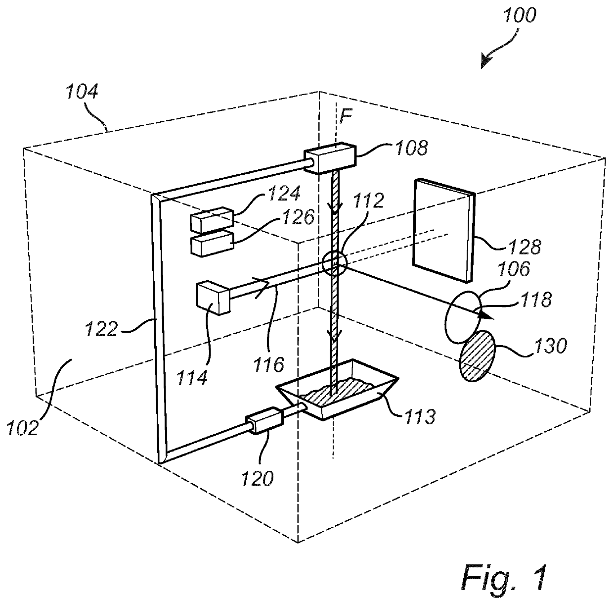
[0076]An X-ray source 100 according to the inventive concept will now be described with reference to FIG. 1.

[0077]As indicated in FIG. 1, a low pressure chamber, or vacuum chamber, 102 may be defined by an enclosure 104 and an X-ray transparent window 106 which separates the low pressure chamber 102 from the ambient atmosphere. The X-ray source 100 comprises a liquid jet generator 108 configured to form a liquid jet 110 moving along a flow axis F. The liquid jet generator 110 may comprise a nozzle through which liquid, such as e.g. liquid metal may be ejected to form the liquid jet 110 propagating towards and through an interaction region 112. The liquid jet 110 propagates through the interaction region 112, towards a collecting arrangement 113 arranged below the liquid jet generator 108 with respect to the flow direction. The X-ray source 100 further comprises an electron source 114 configured to provide an electron beam 116 directed towards the interaction region 112. The electron...


PUM


Abstract

A method for protecting an X-ray source including: a liquid jet generator configured to form a liquid jet moving along a flow axis; an electron source configured to provide an electron beam interacting with the liquid jet to generate X-ray radiation; the method including: generating the liquid jet: monitoring a quality measure indicating a performance of the liquid jet; identifying, based on the quality measure, a malperformance of the liquid jet; and if said malperformance is identified, causing the X-ray source to enter a safe mode for protecting the X ray source. Further, to corresponding devices.

Description

TECHNICAL FIELD[0001]The inventive concept described herein generally relates to electron impact X-ray sources, and in particular to methods for protecting such X-ray sources.BACKGROUND[0002]Systems for generating X-rays by irradiating a liquid jet are described in the applicant's International Applications PCT / EP2012 / 061352 and PCT / EP2009 / 000481. In these systems, an electron gun comprising a high-voltage cathode is utilized to produce an electron beam that impinges on a liquid jet. The target is preferably formed by a liquid metal with low melting point, such as indium, tin, gallium lead or bismuth, or an alloy thereof, provided inside a vacuum chamber. Means for providing the liquid jet may include a heater and / or cooler, a pressurizing means (such as a mechanical pump or a source of chemically inert propellant gas), a nozzle and a receptacle or a collecting arrangement to collect liquid at the end of the jet. The X-ray radiation generated by the interaction between the electron ...

Claims


Application Information

Patent Timeline
IPC IPC(8): H05G2/00H05G1/54
CPCH05G2/003H05G1/54H05G2/008
Inventor TUOHIMAA, TOMITAKMAN, PERLARSSON, DANIEL
Owner EXCILLUM
Why Eureka
Try Eureka