Annular cathode for vacuum tube

Active Publication Date: 2021-01-14
THALES SA
View PDF0 Cites 0 Cited by
  • Summary
  • Abstract
  • Description
  • Claims
  • Application Information

AI Technical Summary

Benefits of technology

[0037]Thus, a good trade-off is obtained between a good thermal resistance (fineness) and a

Problems solved by technology

The main drawback with cathodic electron emitters is the contact with the element which supports it.
This non-uniformity and these deformations affect the quality of the beam emitted by the electron gun.
These expansions are not balanced and there occurs a non-uniformity of the thermal expansion.
At the same time, the presence of discrete contact points between the electron emitter and the traditional connections produces heat flux discontinuities and affects the thermal uniformity of the emitter.
The main difficulties in designing a cathode concern the alignment of the electron emitt

Method used


Image

  • Annular cathode for vacuum tube
  • Annular cathode for vacuum tube
  • Annular cathode for vacuum tube

Examples


Embodiment Construction

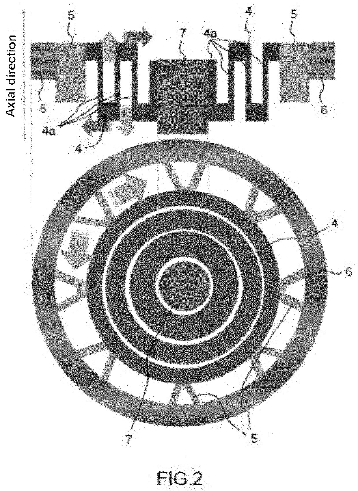
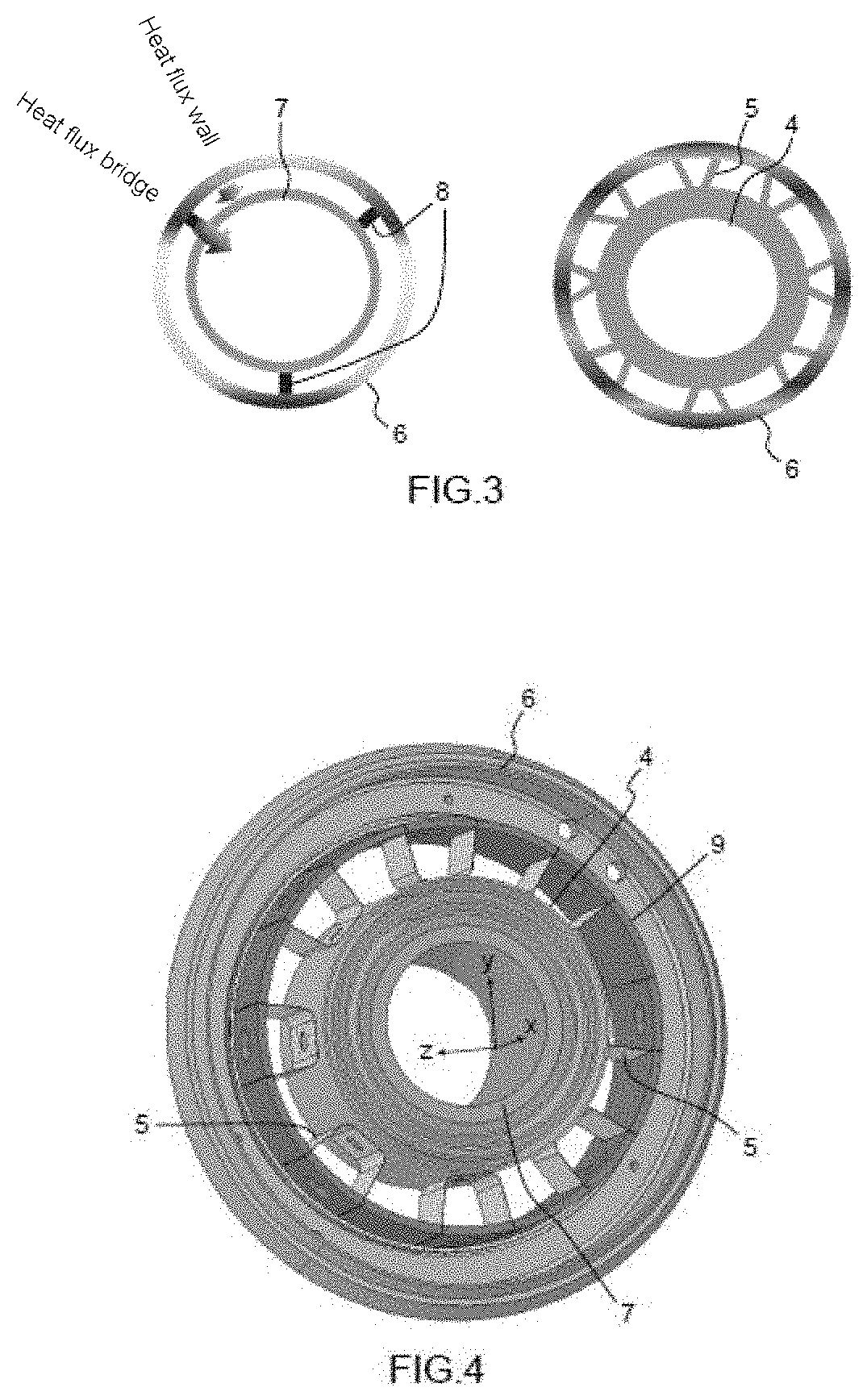
[0046]The proposed invention, as represented in FIG. 2, is based on two coupled mechanical securing elements which act in synergy to maintain the concentricity and the alignment of all the components of the cathode when it is operating hot. The two securing elements are a folded skirt 4 and a plurality of lugs 5 disposed in series between a cylindrical central support 7 whose axis is that of the cathode and an outer peripheral electron emitter 6 with annular section whose axis is that of the cathode, extending over the outer perimeter of the cathode.

[0047]The folded skirt 4 makes it possible to compensate for the axial and radial deformations of the geometry of the cathode. The folded skirt 4 comprises sleeves or concentric tubular cylinders 4a which implement gauged flexible securing elements with opposing thermal expansion vectors to neutralize thermal expansion.

[0048]The plurality of lugs 5 makes it possible to neutralize orbital and radial deformations of the cathode. The lugs 5...


PUM


Abstract

An annular cathode for a vacuum tube includes a central cylindrical support whose axis is that of the cathode; an outer peripheral electron emitter with annular section whose axis is that of the cathode, extending over the outer perimeter of the cathode; and a folded skirt, secured at an inner end to the central support, and secured, at its outer end, to a plurality of lugs; each lug being disposed in series with the folded skirt, and secured with the folded skirt and with the inner surface of the electron emitter.

Description

CROSS-REFERENCE TO RELATED APPLICATIONS[0001]This application claims priority to foreign French patent application No. FR 1907279, filed on Jul. 8, 2019, the disclosure of which is incorporated by reference in its entirety.FIELD OF THE INVENTION[0002]The invention relates to an annular cathode for a vacuum tube or electron tube. The present invention relates to the development of high-performance thermoelectrical / thermoionic electron guns, such as gyrotrons. A gyrotron is a power vacuum tube (oscillator), generating a microwave frequency wave.BACKGROUND[0003]The main drawback with cathodic electron emitters is the contact with the element which supports it.[0004]The electron emitter must be kept in a specific position, but must at the same time be thermally insulated from the rest of the cathode (including the support). In addition, the electron emitter must have a uniform temperature over the whole surface.[0005]The contact of the emitter with the structure which supports it is the...

Claims


Application Information

Patent Timeline
IPC IPC(8): H01J19/12H01J19/48
CPCH01J19/12H01J19/48H01J23/04H01J1/16H01J1/18H01J23/07H01J25/42H01J1/88H01J19/42
Inventor LEGGIERI, ALBERTOLEGRAND, FRANÇOISMARCHESIN, RODOLPHE
Owner THALES SA
Why Eureka
Try Eureka