Supercharge Your Innovation With Domain-Expert AI Agents!

Method and apparatus for the safe limitation of motor torque in a three-phase drive

a three-phase drive and safe limitation technology, applied in the direction of dynamo-electric converter control, dynamo-electric brake control, dynamo-electric gear control, etc., can solve the problem of additional computational complexity in calculation, size and cost of sensor circuits that are significant, and the inclusion of additional current sensors with their attendant size and cost penalties, so as to achieve safe limitation of torque

Active Publication Date: 2021-01-21
KOLLMORGEN CORP
View PDF0 Cites 3 Cited by
  • Summary
  • Abstract
  • Description
  • Claims
  • Application Information

AI Technical Summary

Benefits of technology

The patent describes various ways to sense and control the current in an AC servo motor power stage. The technical effects of these methods include improved performance and safety. The drawings show different ways to place sensors in the motor to achieve better control. A formula is also provided to calculate the current vector from two phase current measurements. Overall, the patent provides technical means to improve the performance and safety of AC servo motors.

Problems solved by technology

There are drives, particularly low voltage drives, on the market using the current sensing arrangement of FIG. 1, however there are reasons why the current sensing arrangement of FIG. 1 is not widely used, particularly at high bus voltages.
One reason is that packaged IGBT inverter bridges such as type FP150R12KT4 from Infineon Semiconductor do not allow the connection of a sensor in series with the emitter of each low side IGBT.
Both types of sensor circuit are of a size and cost that is significant in relation to the product as a whole; therefore there is commercial pressure to use fewer sensors of this type.
Thus there is additional computational complexity when calculating the flux vector for an interior magnet motor but no additional quantities need to be measured over those required for torque estimation for surface magnet motors.
The main disadvantage of this implementation is that it requires inclusion of further current sensors with their attendant size and cost penalties.
Note that there is a variable delay between the current measurement and the subsequent application of voltage; for this reason and because of the two abnormal conditions described below this technique is seldom used for closed loop control.

Method used


Image

  • Method and apparatus for the safe limitation of motor torque in a three-phase drive
  • Method and apparatus for the safe limitation of motor torque in a three-phase drive
  • Method and apparatus for the safe limitation of motor torque in a three-phase drive

Examples


Embodiment Construction

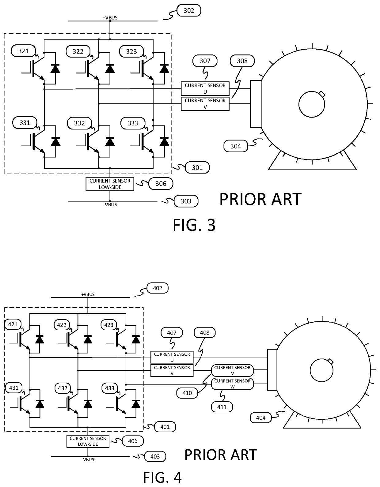
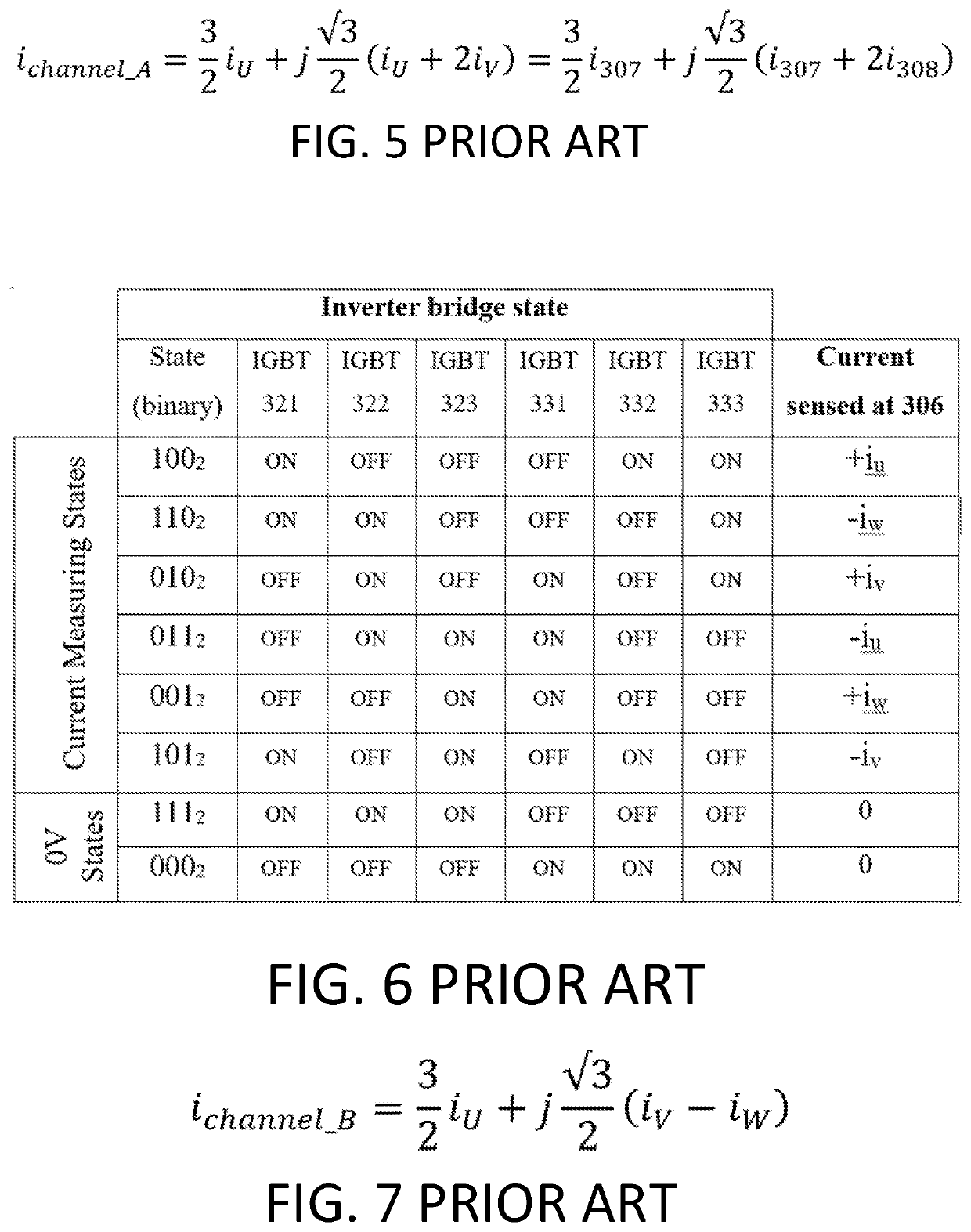
>[0037]This invention makes a two-channel measurement of the current vector using the arrangement of current sensors in FIG. 3. The first safety channel will be termed safety channel A and the second safety channel will be termed safety channel B. The safety sub-system uses the phase current measurements from sensors 307 and 308 to form the current vector for safety channel A using the well-known Clarke transformation from LEONHARD equation (10.4 a) in combination with Kirchoff s current law identity iu+iv+iw≡0 as shown in FIG. 5.

[0038]The current vector for safety channel B is derived from the bus current sensor 306 but here the measurements of the phase currents are discontinuous and are multiplexed through sensor 306 by the inverter bridge 301. This uses the technique of BOYS. For example when IGBTs 321, 332 and 333 are all ON and the remaining IGBTs 322, 323 and 331 are all OFF then the current in sensor 306 is the U phase current with positive polarity. The eight possible state...


PUM


Abstract

A torque-limiting safety circuit servo drive for AC permanent magnet motors including a three-phase inverter bridge, a first current sensor in series with a first motor phase, a second current sensor in series with a second motor phase, a third current sensor in series with the DC bus, and a drive control circuit that controls the six pulse-width modulated gate drive signals for the three-phase inverter bridge. The drive circuit has first and second safety channel STO inputs whereby either channel can shut down the three-phase inverter bridge, emits a signal set to represent the switching state of the three-phase inverter bridge, and modifies the switching pattern of the PWM to ensure the dwell times of PWM is sufficiently long to allow a valid measurement of phase current using the bus current sensor. First and second safety processors controls the first and second safety channel STO inputs, respectively.

Description

RELATED APPLICATIONS[0001]This application claims the benefit of priority to U.S. provisional patent application Ser. No. 62 / 875,320, filed on Jul. 17, 2019. The content of the referenced patent application is incorporated herein by reference in its entirety for any purpose whatsoever.BACKGROUND OF THE INVENTION1. Field of the Invention[0002]This invention is directed toward motor driven shafts found in automated machinery, robots, and other electrically driven equipment. In such equipment it may be necessary to limit the torque or force exerted by the motor in order to avoid damage to personnel or equipment. This invention is equally applicable to rotary permanent magnet synchronous motors or linear permanent magnet synchronous motors.2. State of the Art[0003]Machinery manufactured in the European Union is now required to demonstrate safety against injury by the application of the standards IEC62061 and ISO 13849 and related standards which, in order to mitigate risk, and consisten...

Claims


Application Information

Patent Timeline
Patent Type & Authority Applications(United States)
IPC IPC(8): H02P29/024H02P27/06H02H7/08H02P21/00
CPCH02P29/027H02P21/00H02H7/0833H02P27/06H02P29/032
Inventor PEARCE, ROBERT
Owner KOLLMORGEN CORP
Features
  • R&D
  • Intellectual Property
  • Life Sciences
  • Materials
  • Tech Scout
  • Unparalleled Data Quality
  • Higher Quality Content
  • 60% Fewer Hallucinations
Learn More