Electric motor and electric tool

a technology which is applied in the direction of manufacturing tools, mechanical energy handling, and portable power-driven tools, can solve the problems of poor heat dissipation effect of electric motors and the inability of conventional electric motors to adjust the rotation speed, so as to improve the heat dissipation effect of electric motors and electric tools, and reduce the volume of hall circuit boards

Active Publication Date: 2021-01-28
TECHWAY INDAL
View PDF4 Cites 3 Cited by
  • Summary
  • Abstract
  • Description
  • Claims
  • Application Information

AI Technical Summary

Benefits of technology

The present invention provides an electric motor and electric tool with improved heat dissipation effects. This is achieved through a structural design that reduces the volume of the Hall circuit board and the area blocking the airflow path provided by the heat dissipation unit. Additionally, the setting angle of the Hall circuit board can be changed to adjust the rotation speed of the motor without replacing any parts or hardware equipment.

Problems solved by technology

Because the Hall elements 14 need to be close to the rotor 111 to obtain a better induction effect, plus the positions of the Hall elements 14 are exactly blocking an airflow path provided by the fan 12, the electric motor 11 is poorly ventilated on a side close to the circuit board 13, resulting in poor heat dissipation effect of the electric motor 11.
In addition, except for controlling by means of software, the structure of the conventional electric motor cannot adjust rotation speed.

Method used


Image

  • Electric motor and electric tool
  • Electric motor and electric tool
  • Electric motor and electric tool

Examples


Embodiment Construction

[0035]Before the present invention is described in detail, it should be noted that in the following description, similar elements are denoted by a same number.

[0036]Please refer to FIGS. 4, 5 and 7 for a first preferred embodiment of an electric tool of the present invention including a housing unit 2, an electric motor 3, a Hall unit 4, a wiring circuit unit 5, a control unit 6, a battery unit 7, a heat dissipation unit 8, and a tool head 201 provided in the housing unit 2 and driven by the electric motor 3, as shown in FIG. 15, the tool head 201 is caused to generate rotational output to rotate a workpiece. Among the above components, the tool head is not a technical feature of the present invention, so it will not be described here.

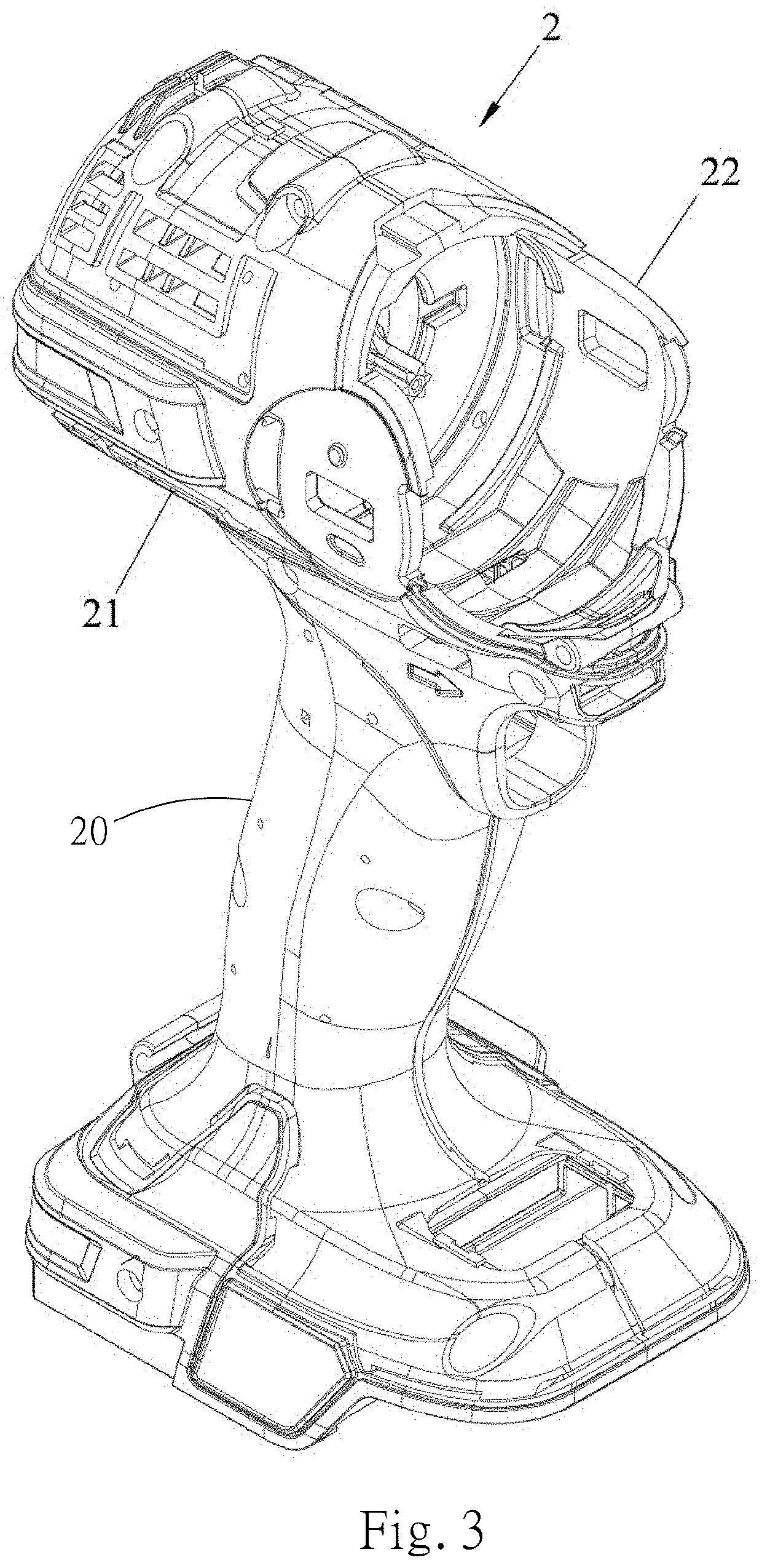
[0037]Please refer to FIGS. 3, 4 and 5. The housing unit 2 includes a first housing 21, a second housing 22 that cooperates with the first housing 21 to define a disposition space 24 for disposing the electric motor 3, the Hall unit 4 and the wiring ci...


PUM


Abstract

The present invention relates to an electric motor and an electric tool equipped with the electric motor. The electric motor includes a rotor, a stator, a coil module wound around the stator, a Hall unit and a wiring circuit unit. The Hall unit includes a Hall circuit board disposed around a rotating shaft of the rotor, and a Hall module for sensing rotation of the rotor. The wiring circuit unit is independent of the Hall circuit board and includes a three-phase power source interface. The wiring circuit unit electrically connects coils of the coil module to the power source interfaces respectively by groups. By separately disposing the Hall unit and the wiring circuit unit independently, a volume of the Hall circuit board can be reduced, and an area blocking an airflow path of a heat dissipation unit can be reduced, so heat dissipation effect of the electric motor and the electric tool can be improved.

Description

BACKGROUND OF THE INVENTIONField of Invention[0001]The present invention relates to components of electric drive, and more particularly refers to an electric motor and an electric tool equipped with the electric motor.Related Art[0002]Electric tools such as electric impact wrenches, electric drill bits, electric screwdrivers, etc. are all commonly used decoration tools. Please refer to FIGS. 1 and 2, the basic framework of a conventional electric tool includes an electric motor 11, a fan 12, a circuit board 13 disposed corresponding to the electric motor 11, three Hall elements 14, and a wiring module 15 with a three-phase power source interface 151.[0003]The electric motor 11 has a rotor 111, a stator 112 surrounding the rotor 111, and a plurality of coils (not shown in the figures) wound around the stator 112.[0004]The circuit board 13 is provided for disposing the Hall elements 14 and the wiring module 15. The Hall elements 14 are provided at an inner circle of the circuit board ...

Claims


Application Information

Patent Timeline
Patent Type & Authority Applications(United States)
IPC IPC(8): H02K11/215H02K7/14H02K9/22H02K11/00H02K11/33B25F5/00
CPCH02K11/215H02K7/145H02K9/22H02K2211/03H02K11/33B25F5/008H02K11/0094H02K2203/09H02K5/225H02K3/522H02K1/148
Inventor CHUNG, FU-HSIANGCHEN, HONG FANGCHEN, WEI-TINGHSU
Owner TECHWAY INDAL
Why Eureka
Try Eureka