Method for heating a catalytic converter and exhaust gas aftertreatment system

a catalytic converter and exhaust gas aftertreatment technology, which is applied in the direction of exhaust treatment electric control, electrical control, machines/engines, etc., can solve the problems of reducing the heat loss of the exhaust gas of the internal combustion engine to the catalytic converter, the comparatively long time passes until the catalytic converter in the underbody position has reached its light-off, and the combustion air ratio of the exhaust gas burner is pilot-controlled. , to achieve the effect of reducing the heat loss

Active Publication Date: 2021-02-11
VOLKSWAGEN AG
View PDF0 Cites 2 Cited by
  • Summary
  • Abstract
  • Description
  • Claims
  • Application Information

AI Technical Summary

Benefits of technology

[0031]According to a further preferred embodiment of the invention, it is provided that the catalytic converter is arranged in a position close to the engine, in particular as a first emission-reducing exhaust gas aftertreatment component in the flow direction of an exhaust gas of the internal combustion engine through the exhaust system. In this context, a position close to the engine means a position with an exhaust gas run length of less than 80 cm, preferably less than 50 cm, from an outlet of the internal combustion engine. In particular, the catalytic converter is arranged directly downstream of a turbine of an exhaust gas turbocharger as the first emission-reducing exhaust gas aftertreatment component. The heat losses of the exhaust gas of the internal combustion engine to the catalytic converter can thus be reduced, as a result of which the exhaust system upstream of the catalytic converter can be heated up in a comparatively short time. The exhaust gas flow from the internal combustion engine can then keep the catalytic converter at a temperature above the light-off temperature, so that after the initial heating by the exhaust gas burner, no further heating operations are necessary or these heating operations can be shortened.
[0032]Alternatively, it is advantageously provided that the catalytic converter is arranged in a position remote from the engine, in particular in an underbody position of a motor vehicle. Using the method according to the invention, even large-volume catalytic converters in an underbody position of a motor vehicle can be heated up to their light-off temperature immediately after a cold start of the internal combustion engine. The thermal load at this position of the exhaust system is lower during high-...

Problems solved by technology

A disadvantage of the arrangement of a catalytic converter in the underbody position, however, is that, due to the long exhaust gas run length between the outlet of the internal combustion engine and the heat losses through the walls of the exhaust gas duct, a comparatively long time passes until a catalytic conve...

Method used


Image

  • Method for heating a catalytic converter and exhaust gas aftertreatment system
  • Method for heating a catalytic converter and exhaust gas aftertreatment system
  • Method for heating a catalytic converter and exhaust gas aftertreatment system

Examples


Embodiment Construction

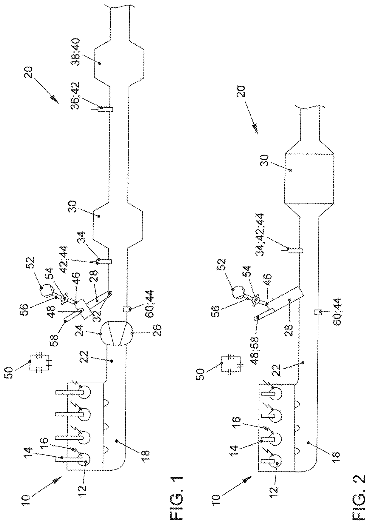
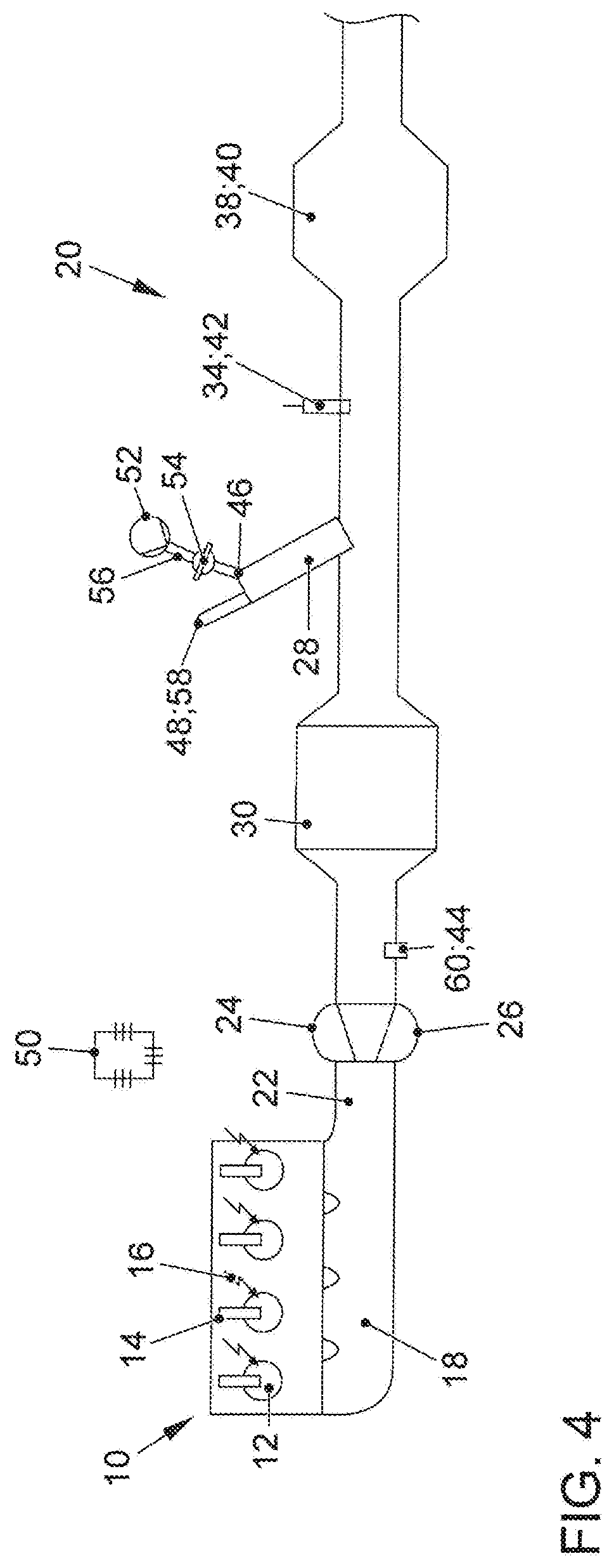
matic illustration of an internal combustion engine 10, the outlet 18 of which is connected to an exhaust system 20 of an exhaust gas aftertreatment system according to the invention for exhaust gas aftertreatment of an exhaust gas stream from the internal combustion engine 10. The internal combustion engine 10 is designed as a gasoline engine, which is spark-ignited by means of external ignition means, in particular by means of spark plugs 16. The internal combustion engine 10 has a plurality of combustion chambers 12, in which a fuel-air mixture is burned. For this purpose, a fuel injector 14 is provided in each case at the combustion chambers 12 in order to inject a fuel into the combustion chambers 12. The internal combustion engine 10 is preferably designed as an internal combustion engine 10 charged by means of an exhaust gas turbocharger 24, wherein a turbine 26 of the exhaust gas turbocharger 24 is arranged downstream of the outlet 18 and upstream of a three-way catalytic co...


PUM


Abstract

A method for heating a catalytic converter in an exhaust system of an internal combustion engine, in which an exhaust gas burner for heating the catalytic converter is arranged, upstream of the catalytic converter. A lambda probe for controlling the combustion air ratio of the exhaust gas burner is arranged immediately downstream of the exhaust gas burner and upstream of the catalytic converter. The method includes operating the internal combustion engine with a stoichiometric combustion air ratio (λE=1), activating the exhaust gas burner, which is operated alternately with a substoichiometric combustion air ratio (λB<1) and a superstoichiometric combustion air ratio (λB>1), wherein from the substoichiometric combustion air ratio (λB<1) to the superstoichiometric combustion air ratio (λB>1) as soon as a rich breakthrough is detected by the second lambda probe (34), and wherein a switchover from the superstoichiometric combustion air ratio (λB>1) to the substoichiometric combustion air ratio (λB<1) takes place as soon as a lean breakthrough is detected by the second lambda probe.

Description

CROSS-REFERENCE TO RELATED APPLICATIONS[0001]This application claims priority from German Patent Application No. 10 2019 121 428.9, filed Aug. 8, 2019, which is incorporated herein by reference in its entirety.FIELD OF THE INVENTION[0002]The invention relates to a method for heating a catalytic converter in an exhaust gas aftertreatment system and an exhaust gas aftertreatment system with a catalytic converter according to the preamble of the independent claims.BACKGROUND OF THE INVENTION[0003]The continual tightening of exhaust gas legislation places high demands on vehicle manufacturers, which can be solved by taking appropriate measures to reduce raw engine emissions and by appropriate exhaust gas aftertreatment. In order to be able to effectively convert the raw emissions, which are not completely avoidable, downstream of the engine, catalytic converters coated with precious metal are installed in the exhaust system of the internal combustion engine. In order for these catalytic...

Claims


Application Information

Patent Timeline
IPC IPC(8): F01N3/20F02D41/14F02D41/06F02D41/02F01N3/10
CPCF01N3/2033F02D41/1454F01N3/101F02D41/0255F02D41/064F01N9/00F01N11/00F01N11/007F01N2430/06F01N2240/14F01N13/009F01N3/035F01N3/025F01N2560/025F01N2560/14Y02T10/40
Inventor BARON VON CEUMERN-LINDENSTJERNA, FALK-CHRISTIANPAUKNER, STEFANKAACK, MICHAEL
Owner VOLKSWAGEN AG
Why Eureka
Try Eureka