Filter and multiplexer
a filter and multiplexer technology, applied in the field of filters and multiplexers, can solve the problems of difficult to achieve sufficient attenuation characteristics and isolation characteristics, and achieve the effect of excellent attenuation characteristics and low loss
- Summary
- Abstract
- Description
- Claims
- Application Information
AI Technical Summary
Benefits of technology
Problems solved by technology
Method used
Image


Examples
first preferred embodiment
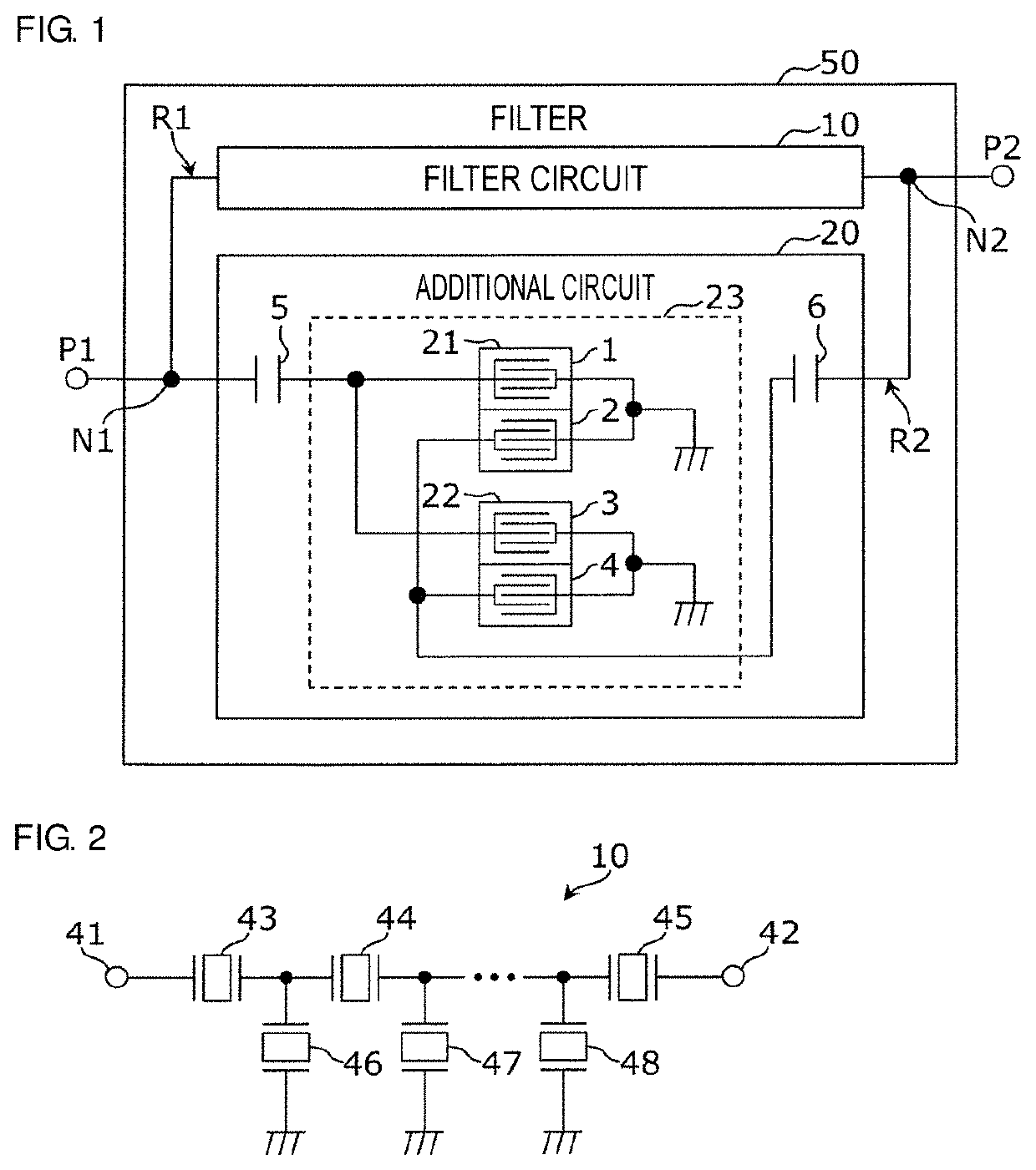
[0019]A filter according to a first preferred embodiment of the present invention will now be described, providing an example of a filter in which a filter circuit having a pass band is connected in parallel to an additional circuit that generates a signal (hereinafter referred to as a cancel signal) having a phase opposite to that of a signal component outside the pass band, which is transmitted through the filter circuit.
[0020]FIG. 1 is a circuit diagram illustrating an exemplary configuration of a filter according to the first preferred embodiment. As illustrated in FIG. 1, a filter 50 includes terminals P1 and P2, a filter circuit 10, and an additional circuit 20.
[0021]A radio-frequency signal is transmitted through the terminals P1 and P2. The direction in which the radio-frequency signal is transmitted between the terminals P1 and P2 is not limited.
[0022]The filter circuit 10 is a filter having a pass band and is, for example, a band pass filter, a low pass filter, or a high p...
second preferred embodiment
[0056]In a second preferred embodiment of the present invention, a multiplexer including the additional circuit 20 described in the first preferred embodiment will be described.
[0057]FIG. 6 is a circuit diagram illustrating an exemplary configuration of a multiplexer according to the second preferred embodiment. As illustrated in FIG. 6, a multiplexer 60 includes terminals ANT, Tx, and Rx, a transmission filter circuit 11, a reception filter circuit 12, and the additional circuit 20. In the multiplexer 60, the transmission filter circuit 11 and the additional circuit 20 define a transmission filter 51 and the reception filter circuit 12 defines a reception filter 52.
[0058]The transmission filter 51 is the same or substantially the same as the filter 50 in FIG. 1. Specifically, the transmission filter 51 results from replacement of the filter circuit 10 in the filter 50 with the transmission filter circuit 11. The multiplexer 60 is defined by connecting one end of the transmission fi...
PUM
 Abstract
Description
Claims
Application Information