
3D high speed RF beam scanner for hadron therapy

a high-speed rf beam and scanner technology, applied in accelerators, radiation therapy, radiation therapy, etc., can solve the problems of increasing the overall treatment time, slow energy scanning rate, and large gantry support gantries, so as to achieve cost/size savings and increase patient throughput

Pending Publication Date: 2021-03-04
THE BOARD OF TRUSTEES OF THE LELAND STANFORD JUNIOR UNIV
View PDF0 Cites 2 Cited by
  • Summary
  • Abstract
  • Description
  • Claims
  • Application Information

AI Technical Summary

Benefits of technology

The present invention is a system that uses a compact beam delivery system to deliver protons or ion beams up to carbon with a rapid 3D scanning over a tumor volume of up to 4 liters in both transverse and longitudinal dimensions. The system utilizes RF energy modulation and deflection to enable a dose delivery of 50 Gy / L / s, which is a major clinical advantage in treating tumors affected by internal motion. The system provides fast irradiation with benefits to patients such as solving the issue of patient motion and thus removing the need for tracking organ motion during irradiation (motion-adapted radiation therapy). The system can be used with any accelerator delivering a fixed energy proton / hadron beam and can be adapted for use with different hadron sources. The system also utilizes RF technologies with components light and small enough to fit on a movable gantry, allowing the system to deliver the beam at the best angle for the patient and still fit in a treatment room. The system can be used with more than one beamline to accommodate multiple energy ranges each optimized for treating a certain body region, with the goal of achieving higher patient throughput with cost / size savings.

Problems solved by technology

However, the accelerators as well as the gantries supporting the beam delivery systems are significantly larger and more expensive than conventional radiation therapy machines and gantries.
Besides the obvious problems with size and cost with these large systems, the beam also has a slow energy scanning rate, which increases the overall treatment time and makes the treatment plan susceptible to patient motion.
In addition, the full potential of these machines is compromised because the slow methods used to adjust beam energies, also introduce additional energy and momentum spread in the beam.

Method used


Image

  • 3D high speed RF beam scanner for hadron therapy
  • 3D high speed RF beam scanner for hadron therapy
  • 3D high speed RF beam scanner for hadron therapy

Examples


Embodiment Construction

[0049]The present invention can be further understood by the following detailed descriptions of various concepts and the accompanying figures noted above. It is understood that the invention is not limited to the following exemplary embodiments and that variations can be realized in accordance with the concepts described herein.

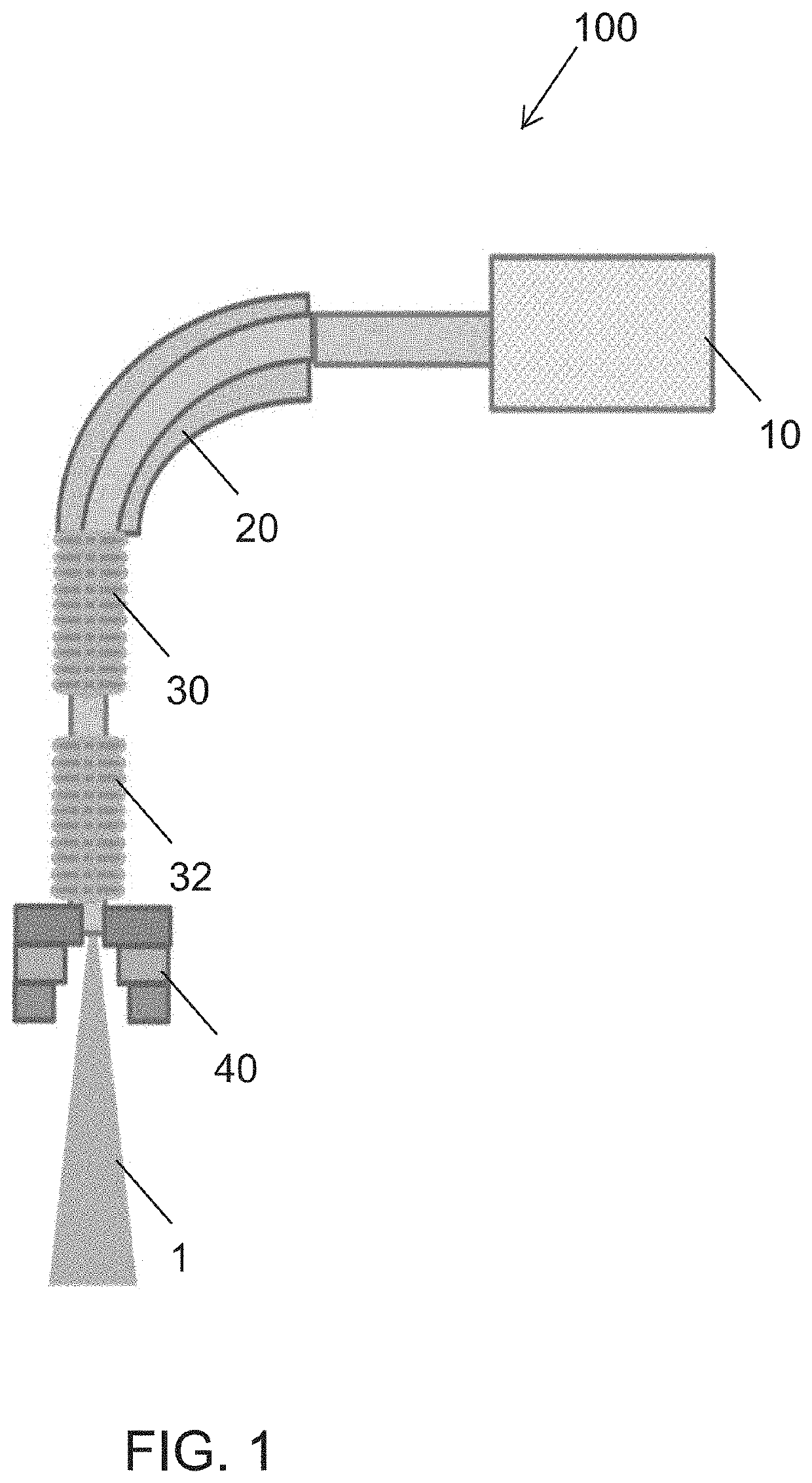
[0050]FIG. 1 shows a schematic of an example gantry system 100. The system includes a hadron source / accelerator 10, transfer portion 20, RF energy modulator 30, RF deflector 32, and magnetic quadrupole 40. The gantry is fed by an accelerator delivering a fixed energy hadron beam and the RF structures operate to scan and deliver the hadron therapy beam 1 rapidly to the targeted tissue in the patient at a high dose. The hadron source / accelerator 10 is configured to deliver a hadron beam at a desired energy suitable for therapy 50-400 MeV. The transfer portion 20 transfers the hadron beam to the gantry, for example, by use of one or more permanent magnets that b...


PUM


Abstract

A hadron therapy system that provides 3D scanning and rapid delivery of a high dose. Such systems can include a hadron source and accelerator with an RF energy modulator and an RF deflector that operate in combination to provide 3D scanning of a targeted tissue. The systems can include a permanent magnet quadrupole for magnification of the beam. The systems can include high energy hadron sources that utilize a multi-cell, multi-klystron design that achieves scanning of high energy hadron beams, for example a fixed energy of 200 MeV protons. Such systems can provide full irradiation of a liter scale tumor within one second or less.

Description

CROSS-REFERENCES TO RELATED APPLICATIONS[0001]This application claims the benefit of U.S. Provisional Patent Application No. 62 / 894,491, filed Aug. 30, 2019, which is hereby incorporated by reference in its entirety for all purposes.STATEMENT AS TO RIGHTS TO INVENTIONS MADE UNDER FEDERALLY SPONSORED RESEARCH AND DEVELOPMENT[0002]This invention was made with Government support under contract DE-AC02-76SF00515 awarded by the Department of Energy. The Government has certain rights in the invention.BACKGROUND OF THE INVENTION[0003]Treatment of cancer using hadron particle beams (protons and light ions) has significant advantages over treatments using photons. However, the accelerators as well as the gantries supporting the beam delivery systems are significantly larger and more expensive than conventional radiation therapy machines and gantries. Besides the obvious problems with size and cost with these large systems, the beam also has a slow energy scanning rate, which increases the ov...

Claims


Application Information

Patent Timeline
IPC IPC(8): A61N5/10H05H7/00H05H7/02H05H7/04
CPCA61N5/1043A61N5/1077H05H7/001H05H2007/045H05H7/04A61N2005/1087H05H2007/025H05H7/02H05H2007/004H05H2007/043H05H2007/007H05H7/18
Inventor TANTAWI, SAMI G.NANNI, EMILIOLI, ZENGHAILIMBORG-DEPREY, CECILE
Owner THE BOARD OF TRUSTEES OF THE LELAND STANFORD JUNIOR UNIV
Learn More